Page 34
A6 Enthalpy Control LEDs
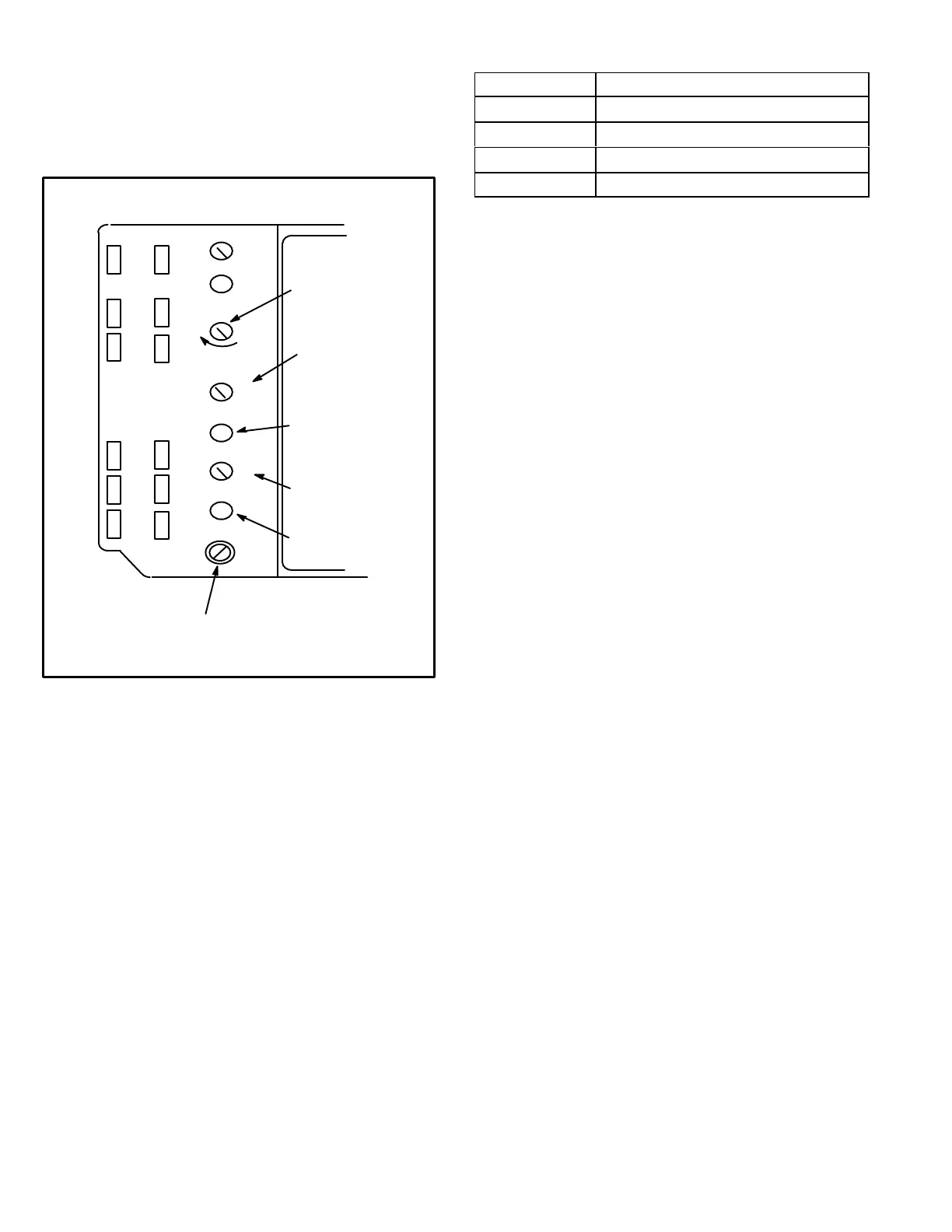
A steady green Free Cool LED indicates that outdoor air is
suitable for free cooling.
When an optional IAQ sensor is installed, a steady green
DCV LED indicates that the IAQ reading is higher than set
point requiring more fresh air. See figure 28.
FIGURE 28
A6 ENTHALPY CONTROLLER
A
B
C
D
Open
Min
Pos
FREE COOLING SETPOINT;
A=Completely counterclockwise
D=Completely clockwise
OUTDOOR AIR
SUITABLE LED
Free
Cool
DCV
EXH
EXH
Set
2V 10V
DCV
Max
2V 10V
DCV
Set
2V 10V
IAQ SETPOINT
IAQ READING IS
ABOVE SETPOINT
DAMPER
MINIMUM
POSITION
IAQ MAXIMUM
POSITION
(set higher than
minimum position)
Free Cooling Setpoint
Outdoor air is considered suitable when temperature and
humidity are less than the free cooling setpoints shown in
table 15. Setting A is recommended. See figure 28. At set
ting A, free cooling will be energized when outdoor air is ap
proximately 73°F (23°C) and 50% relative humidity. If in
door air is too warm or humid, lower the setpoint to B. At
setting B, free cooling will be energized at 70°F (21°C) and
50% relative humidity.
When an optional A62 differential sensor is installed, turn
A6 enthalpy control free cooling setpoint potentiometer
completely clockwise to position “D”.
TABLE 15
ENTHALPY CONTROL SETPOINTS
Control Setting Free Cooling Setpoint At 50% RH
A
73° F (23° C)
B
70° F (21° C)
C
67° F (19° C)
D
63° F (17° C)
Damper Minimum Position
NOTE - A jumper is factory-installed between TB1 R and
OC terminals to maintain occupied status (allowing mini
mum fresh air). When using an electronic thermostat or
energy management system with an occupied/unoccu
pied feature, remove jumper.
1- Set thermostat to occupied mode if the feature is avail
able. Make sure jumper is in place between TB1 termi
nals R and OC if using a thermostat which does not
have the feature.
2- Rotate MIN POS SET potentiometer to approximate
desired fresh air percentage.
NOTE - Damper minimum position can be set lower than
traditional minimum air requirements when an IAQ sensor
is specified. Dampers will open to DCV MAX setting (if CO2
is above setpoint) to meet traditional ventilation require
ments.
3- Measure outdoor air temperature. Mark the point on
the bottom line of chart 1 and label the point “A” (40_F,
4_C shown).
4- Measure return air temperature. Mark that point on the
top line of chart 1 and label the point “B” (74_F, 2 3 _C
shown).
5- Measure mixed air (outdoor and return air) tempera
ture. Mark that point on the top line of chart 1 and label
point “C” (70_F, 21_C shown).
6- Draw a straight line between points A and B.
7- Draw a vertical line through point C.
8- Draw a horizontal line where the two lines meet. Read
the percent of fresh air intake on the side.
9- If fresh air percentage is less than desired, adjust MIN
POS SET potentiometer higher. If fresh air percentage
is more than desired, adjust MIN POS SET poten
tiometer lower. Repeat steps 3 through 8 until calcula
tion reads desired fresh air percentage.
 Loading...
