Page 47
exhaust air pressure relief and also runs when return air
dampers are closed and the supply air blower is operating.
See installation instructions for more detail.
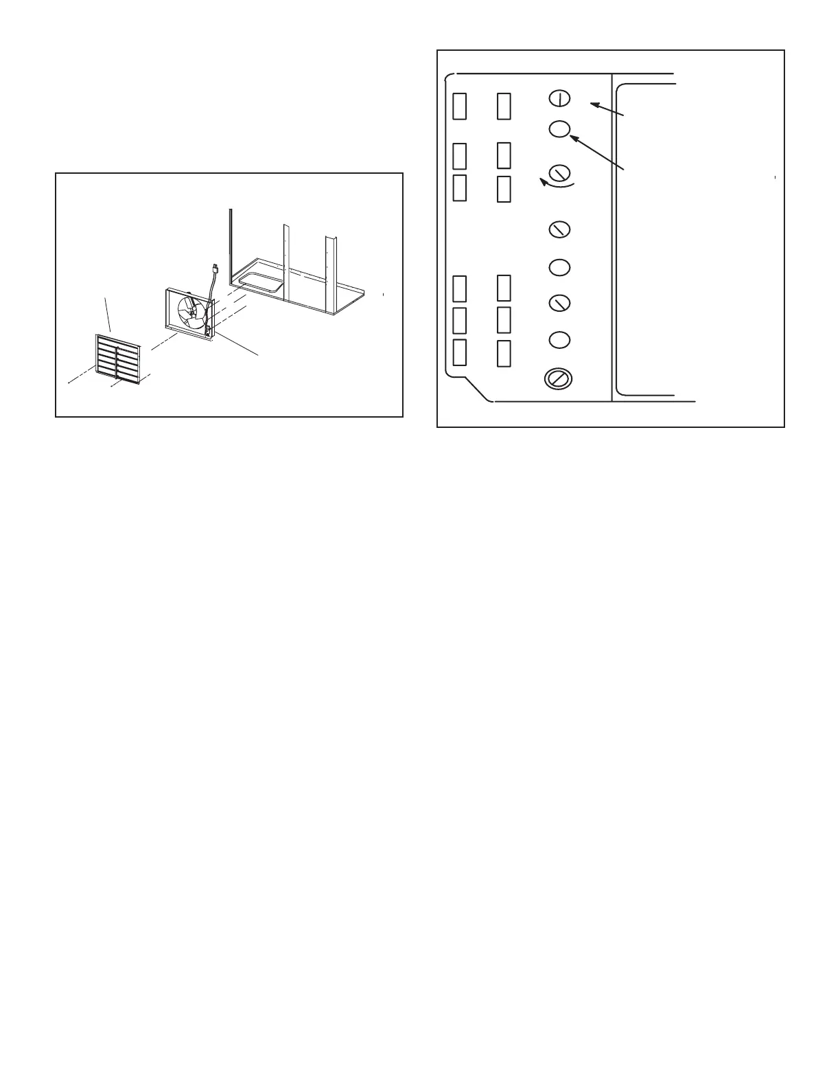
POWER EXHAUST FAN AND
BAROMETRIC RELIEF DAMPER INSTALLATION
POWER
EXHAUST FAN ASSEMBLY
(ORDERED SEPARATELY)
BAROMETRIC
RELIEF
P18
DAMPERS
FIGURE 38
Locate the A6 enthalpy control in the control area. The
EXH SET potentiometer is factory-set at approximately
fans will be energized 30 seconds after dampers are
are further open. Adjust the EXH SET potentiometer lower
K-Optional Cold Weather Kit (Canada only)
Electric heater is available to automatically control the
minimum temperature in the gas burner compartment.
The kit includes the following parts:
1 -
transformer mounted in the blower compartment.
2 -
3 -
possible to the gas valve. It is wired in series with
4 - A thermostat mounting box is installed on the
vestibule of the heating compartment. Included in
the box are the following thermostat switches:
A6 ENTHALPY CONTROLLER
A
B
C
D
Open
Min
Pos
Free
Cool
DCV
EXH
EXH
Set
2V 10V
DCV
Max
2V 10V
DCV
Set
2V 10V
ADJUST POWER
EXHAUST FAN
SETPOINT
ENERGIZED WHEN
DAMPER POSITION
IS HIGHER THAN
EXHAUST FAN
SETPOINT
FIGURE 39
a
switch which opens on a temperature drop. The switch
is wired in series with 24V power and the combustion
-
tion is de-energized. The switch automatically resets
when the heating compartment temperature reaches
switch which opens on a temperature rise. The switch
-
and the electric heater is de-energized. The switch au-
tomatically resets when the heating compartment tem-
switch which closes on a temperature drop. The switch
-
tric heater is energized. The switch automatically opens
L-Control Systems
All thermostat wiring is connected to TB1 located in the
control area. Each thermostat has additional control op-
tions available. See thermostat installation instructions for
more detail.
M-Smoke Detectors A171 and A172
The smoke detectors can be installed in the supply air
supply and return air sections.

 Loading...