Page 22
I−UNIT COMPONENTS
The KHA unit parts arrangement are shown in figure 1. All
L1, L2 and L3 wiring is color coded; L1 is red, L2 is yellow
and L3 is blue. See wiring diagrams in the back of this manu-
al for complete call out of components.
A−Control Box Components
KHA control box components are shown in figure 2. The
control box is located in the upper portion of the compres-
sor compartment.
1−Terminal Strip TB1
All indoor thermostat connections will be to TB1 located in
the control box.
2−Transformer T1
All KHA series units use a single line voltage to 24VAC
transformer mounted in the control box. Transformer
supplies power to control circuits in the unit. The trans-
former is rated at 70VA and is protected by a 3.5 amp cir-
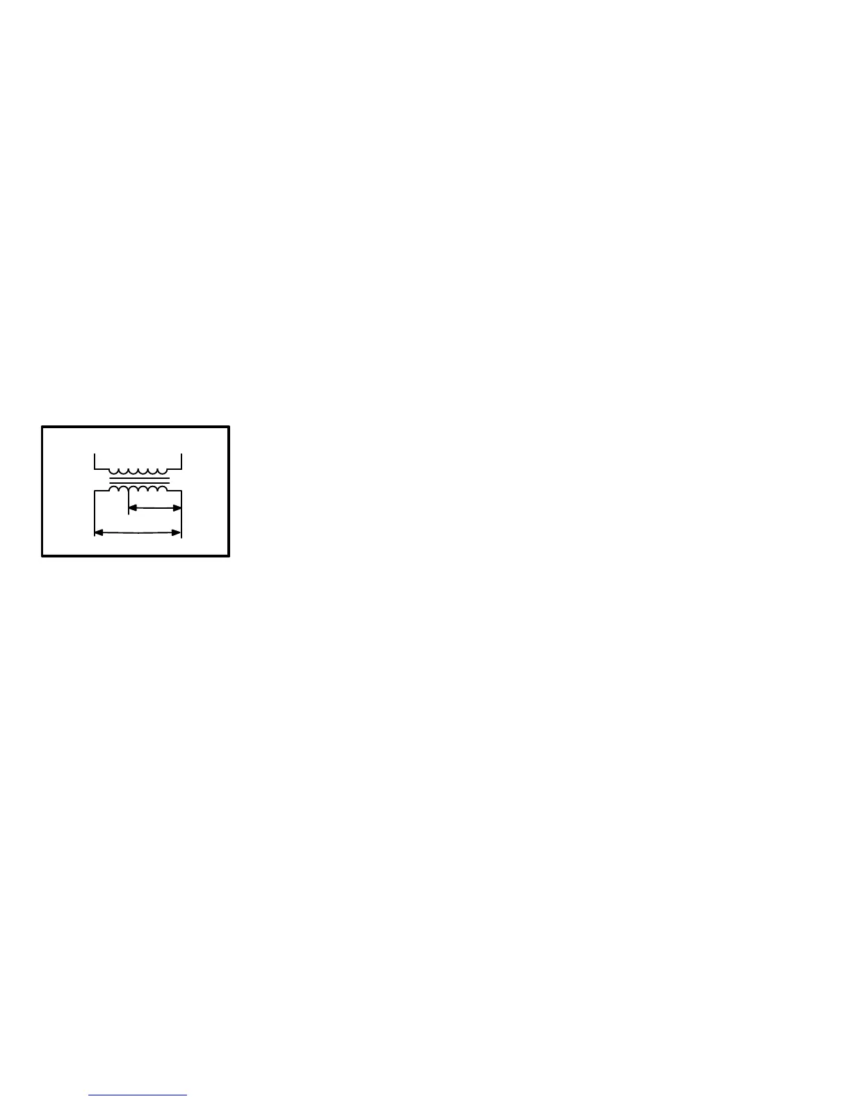
cuit breaker (CB8). The 208/230 (Y) voltage transform-
ers use two primary
voltage taps as shown
in figure 3, while 460
(G) and 575 (J) voltage
transformers use a
single primary voltage
tap.
3−Outdoor Fan Capacitor C1 (Y, G, J & M)
Fan capacitors C1 is used to assist in the start up of con-
denser fan motor B4. Capacitor ratings will be on outdoor fan
motor nameplate.
4−Dual Capacitor C12 (Single Phase)
A single dual capacitor is used for both the outdoor fan and
compressor (see unit diagram). The fan side and the compres-
sor side have different MFD ratings. See side of capacitor for
ratings,.
5−Compressor Contactor K1
K1 is a 24V line voltage contactor used to energize the
compressor and in some cases (P and Y voltage) con-
denser fan in response to thermostat demand. Single
phase units use single−pole double break contactors
and three phase units use three−pole double break con-
tactors.
6−Low Ambient Kit Relay K58
(option used with S11 low ambient switch)
Low ambient relay K58 is a N.C.DPDT relay with a 24V
coil wired in parallel with reversing valve L1. When L1 is
energized in the cooling cycle, K58 is also energized
opening K58−1. Therefore, K58−1 is always closed dur-
ing heating demand bypassing S11. This allows the fan
to operate during the heating demand and cycle during
the cooling demand.
7−Blower Contactor K3
Blower contactor K3 is used in all units. K3 has a 24V coil used
to energize the indoor blower motor in response to blower de-
mand. In single phase units K3 is a single−pole contactor and in
three phase units K3 is a two−pole contactor.
8−Transfer Relay K8
K8 is a two−pole relay with a 24V coil used to de−energize the
reversing valve during a heat call. On a first stage heat call
K8−1 closes de−energizing the reversing valve and K8−2 closes
energizing Y1 on the CMC1 board. Without K8 the reversing
valve would remain energized at all times.
9−Outdoor Fan Relay K10 G, J & M Voltage
Outdoor fan relay K10 is a DPDT relay switch with a 24VAC
coil. K10 energizes condenser fan motor B4 in response to a
heating or cooling demand.
10−Transformer T4 (J voltage)
All (J) 575 voltage units use transformer T4 mounted in the
control box. T4 is a line voltage to 460V to power the indoor
blower. It is connected to line voltage and is powered at all
times.
FIGURE 3
PINK GRAY
ORANGE GRAY
230 VOLTS
208 VOLTS
PRIMARY
SECONDARY
208/230V TRANSFORMER

 Loading...