Page 27
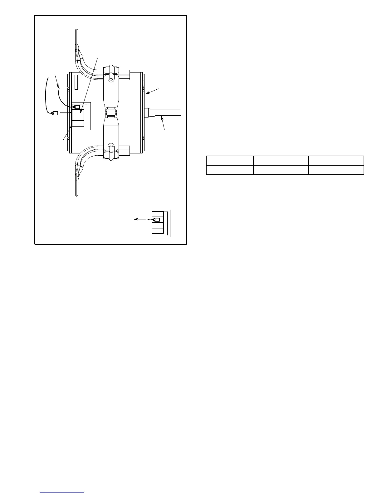
FIGURE 7
MOVE CONNECTOR TO
TERMINAL 2 FOR HIGH
STATIC APPLICATIONS
1
2
3
4
BLOWER
MOTOR
SPEED
TAPS
BLOWER
SHAFT
DIRECT DRIVE HIGH STATIC APPLICATIONS
TERMINAL 1
REMAINS AT
COMMON
1
2
3
4
460/575V UNITS:
Disconnect isolation lead before
moving speed tap wire. Tape exposed
end of isolation lead and secure away
from other components.
C−Determining Unit CFM − Belt Drive Blowers
1− The following measurements must be made with air fil-
ters in place and no cooling demand.
2− With all access panels in place, measure static pres-
sure external to unit (from supply to return).
3− Measure the indoor blower wheel RPM.
4− Referring to the blower tables starting on Page 7 use
static pressure and RPM readings to determine unit
CFM. Use air resistance table on Page 13 when instal-
ling units with any of the options or accessories listed.
5− The blower RPM can be adjusted at the motor pulley.
Loosen Allen screw and turn adjustable pulley clock-
wise to increase CFM. Turn counterclockwise to de-
crease CFM. See figure 8. Do not exceed minimum and
maximum number of pulley turns as shown in table 2.
TABLE 2
MINIMUM AND MAXIMUM PULLEY ADJUSTMENT
Belt Min. Turns Open Max. Turns Open
A Section No minimum 5
D−Blower Belt Adjustment
Maximum life and wear can be obtained from belts only if
proper pulley alignment and belt tension are main-
tained. Tension new belts after a 24−48 hour period of
operation. This will allow belt to stretch and seat
grooves. Make sure blower and motor pulley are aligned as
shown in figure 9.
1− Loosen four bolts securing motor base to mounting
frame. See figure 8.
2− To increase belt tension −
Slide blower motor downward to tighten the belt. This
increases the distance between the blower motor and
the blower housing.
3− To loosen belt tension −
Slide blower motor upward to loosen the belt. This de-
creases the distance between the blower motor and
the blower housing.
4− Tighten four bolts securing motor base to the mounting
frame.

 Loading...