Page 9
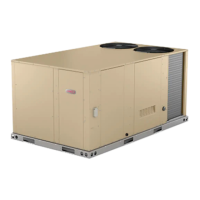
STANDARD BLOWER ASSEMBLY
FIGURE 10
PULLEY
MOTOR
SIDE VIEW
ALLEN
SCREW
BELT ADJUSTING BOLTS
- TURN CLOCKWISE
TO TIGHTEN BELT
MOTOR MOUNTING
BASE
LOOSEN BEFORE
ADJUSTING BELT TENSION
(TWO EACH SIDE)
REMOVE TWO SCREWS ON EACH
SIDE TO SLIDE FRAME PARTIALLY
OUT OF UNIT FOR SERVICE ACCESS
MOTOR
BLOWER
HOUSING
BLOWER
FRAME
GAP BETWEEN
EDGES SHOULD BE
PARALLEL ON BOTH
ENDS BEFORE
TIGHTENING MOTOR
MOUNTING BASE IN
PLACE
REMOVE TWO SCREWS
TO COMPLETELY SLIDE
BLOWER OUT OF UNIT
TO INCREASE BELT TENSION
1- Loosen four bolts securing motor mounting base
to frame.
2- Turn adjusting bolt to the right, or clockwise, to
move the motor away from the blower housing.
IMPORTANT - Gap between end of frame and motor
mounting base should be equal at both ends, i.e. par
allel along gap.
3- Tighten four bolts securing motor mounting base
to frame.
4- Relieve tension on two adjusting bolts.
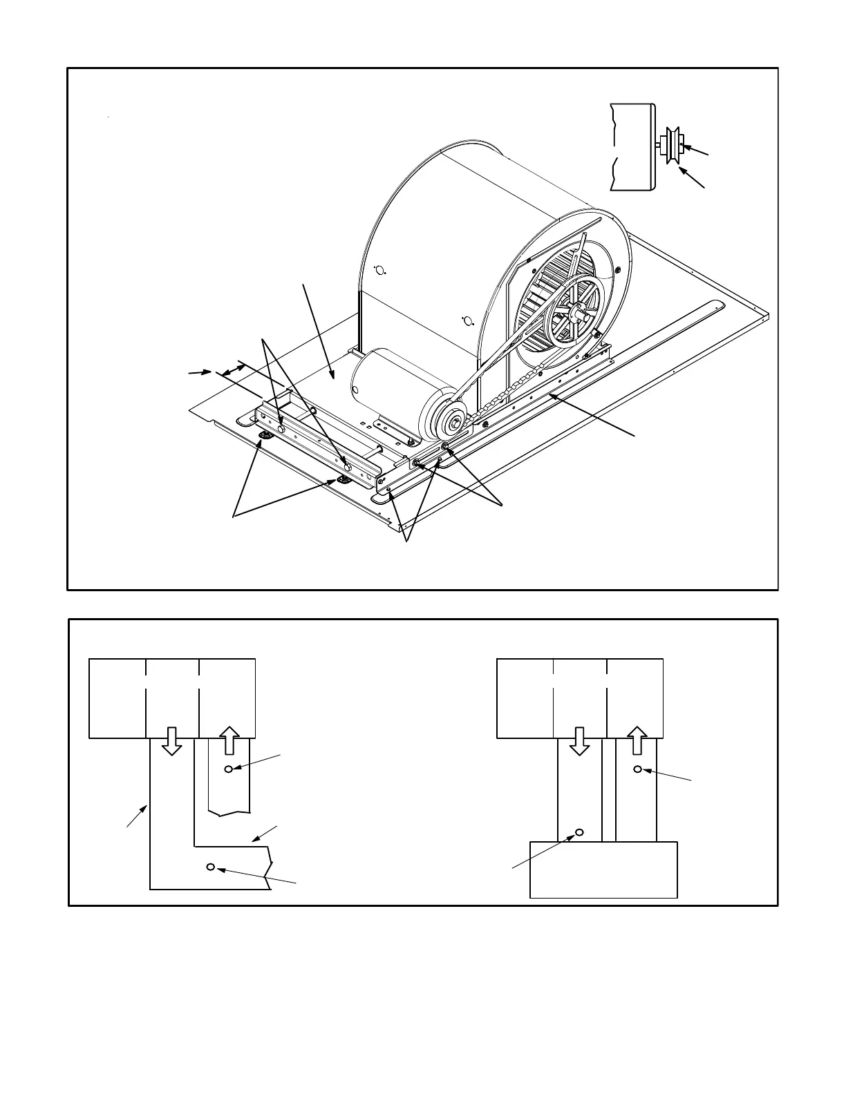
FIGURE 11
LOCATION OF STATIC PRESSURE READINGS
SUPPLY AIR
READING
LOCATION
SUPPLY
RE
TURN
INSTALLATIONS WITH DUCTWORK
SUPPLY
RE
TURN
INSTALLATIONS WITH CEILING DIFFUSERS
MAIN
DUCT RUN
FIRST BRANCH
OFF OF MAIN RUN
DIFFUSER
ROOFTOP UNIT
ROOFTOP UNIT
SUPPLY AIR
READING
LOCATION
RETURN AIR
READING LOCATION
RETURN AIR
READING
LOCATION