Page 42
3-High Temperature Limit S20 and S157 (Secondary)
S20 and S157 are SPST N.C. manual‐reset thermostat s.
S20 and S157 are wired in series with the heating ele
ments. See E1EH wiring diagrams. When S20 or S157
open, power is interrupted to the heating elements which
are wired in series with the limits. K15/K16 are only de-en
ergized when S15 opens. When the contactors are de‐en
ergized, all stages of heat are de‐energized. The thermo
stat is factory set to open at 220_F +
6_F (104_C +
3.3_C) on a temperature rise and can be manually reset
when temperature falls below 160_F (71.0_C). See figure
14 for location.
4-Terminal Strip TB2
Terminal strip TB2 is used for single point power installa
tions only. TB2 distributes power to TB3. Units with multi-
point power connections will not use TB2.
5-Terminal Strip TB3
P and Y voltage units are equipped with terminal strip
TB3. Electric heat line voltage connections are made
to TB3, which distributes power to the electric heat
components and is located on the vestibule. See fig
ure 14.
6-Heating Elements HE1 through HE6
Heating elements are composed of helix wound bare
nichrome wire exposed directly to the air stream. Three
elements are connected in a three‐phase arrange
ment. The elements in 208/230V units are connected in
a “Delta” arrangement. Elements in 460 and 575V units
are connected in “Wye” arrangement. Each stage is
energized independently by the corresponding contac
tors located on the electric heat vestibule panel. Once
energized, heat transfer is instantaneous. High tem
perature protection is provided by primary and redun
dant high temperature limits and overcurrent protec
tion is provided by fuses.
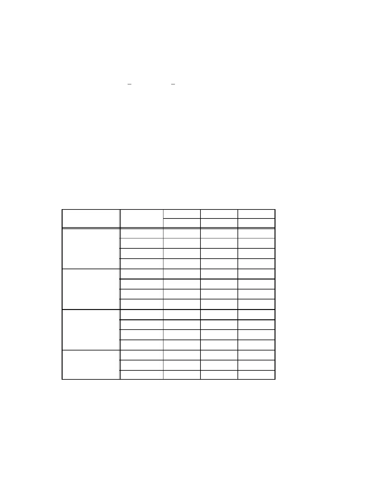
7-Fuse F3
Fuse F3 is housed in a fuse block which holds two or
three fuses. Each F3 fuse is connected in series with
each leg of electric heat. Figure 14 and table 6 show
the fuses used with each electric heat section.
8-Unit Fuse Block & Fuse F4
Three line voltage fuses F4 provide short circuit and
ground fault protection to all cooling components in the
LCH units with electric heat. The fuses are rated in accor
dance with the amperage of the cooling components. The
F 4 fuse block is located inside a sheet metal enclosure .
TABLE 6
Unit
Voltage-
Phase
FUSE Qty Qty
F3 each total
E1EH0075
208/230V-1P 40 A-250V 2 2
208/230V-3P 25 A-250V 3 3
460V-3P 15 A-600V 3 3
575V-3P 15 A-600V 3 3
E1EH0150
208/230V-1P 40 A-250V 2 4
208/230V-3P 50 A-250V 3 3
460V 25 A-600V 3 3
575V 20 A-600V 3 3
E1EH0225
208/230V-1P 40 A-250V 3 6
208/230V-3P 45 A-250V 3 6
460V-3P 35 A-600V 3 3
575V-3P 30 A-600V 3 3
E1EH0300
208/230V-3P 60 A-250V 3 6
460V-3P 50 A-600V 3 3
575V-3P 40 A-600V 3 3