Page 36
C-Blower Compartment
LCH036H, 048H, and 060H units are equipped with direct
drive blowers. LCH036S, 048S, 060S, -074 units are
equipped with two-speed, belt drive blowers. LCH072H
units are equipped with a single-speed belt drive blower.
See unit nameplate for blower type. The blower compart
ment in all LCH036-074 units is located between the evapo
rator coil and the compressor compartment.
1-Blower Wheels
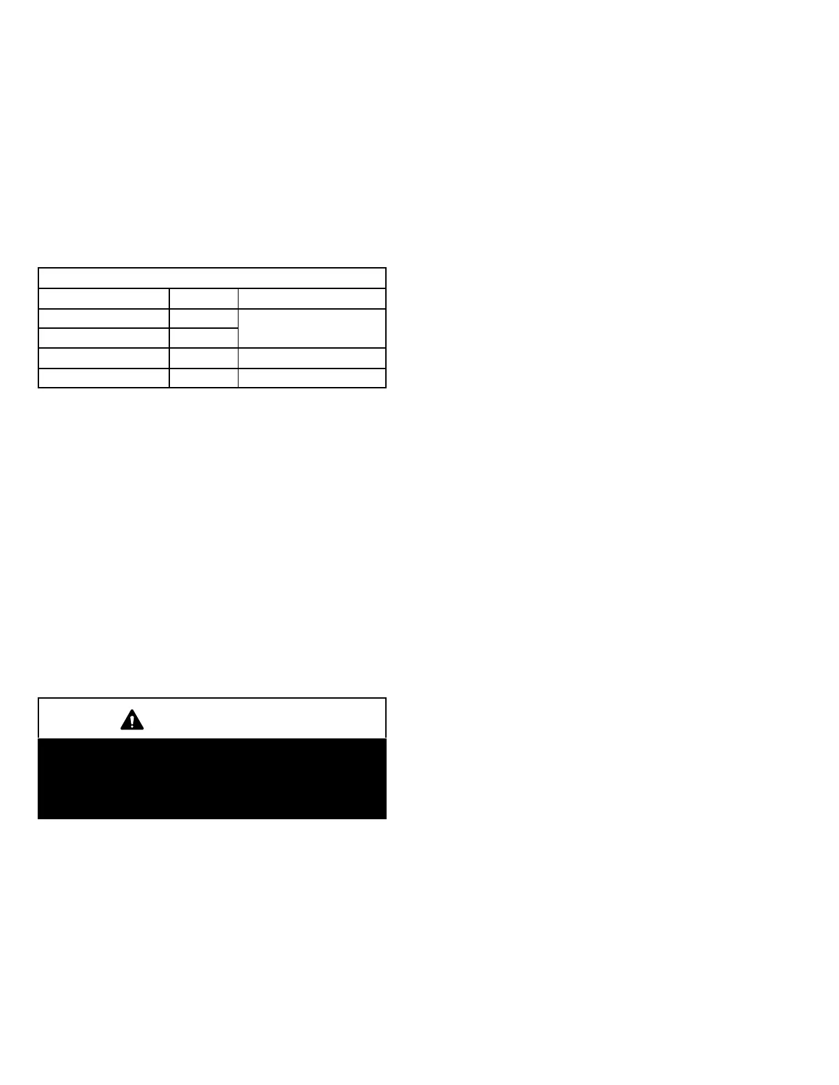
See table 1 for blower wheel type and size.
TABLE 1
BLOWER WHEELS
LCH Unit Type Size - in. (mm)
036S, 048S, 060S Belt
10 X 10 (254 X 254)
036H, 048H Direct
060H Direct 11 X 10 (279 X 254)
072H, 074H Belt 15 X 9 (381 X 229)
2-Indoor Blower Motor B3
All direct drive blower motors are electronically commu
tated, brushless, DC motors. Belt drive blower motors are
single (6-ton) or two-speed (3, 4, 5 and 6 ton) integral mo
tors. Low speed is approximately 2/3 of high speed. CFM
adjustments on belt drive units are made by adjusting the
motor pulley (sheave). CFM adjustments on direct drive
units are made by changing ECTO parameters as shown in
the Unit Controller manual provided with each unit. Motors
are equipped with sealed ball bearings. All motor specifica
tions are listed in the SPECIFICATIONS (table of contents)
in the front of this manual. Units may be equipped with mo
tors manufactured by various manufacturers, therefore
electrical FLA and LRA specifications will vary. See unit rat
ing plate for information specific to your unit.
IMPORTANT
Three phase scroll compressors must be phased se
quentially for correct compressor and blower rota
tion. Follow “COOLING START-UP” section of instal
lation instructions to ensure proper compressor and
blower operation.
A-Blower Operation
Refer to the Unit Controller Installation and Setup Guide to
energize blower. Use the menu navigation arrows and se
lect button; see Service - Test.
B-Determining Unit CFM
1- The following measurements must be made with air fil
ters in place.
IMPORTANT - On units equipped with direct drive blowers,
determine and adjust high speed CFM before low speed
CFM. Low speed CFM should be adjusted to 2/3 of high
speed CFM. A low speed adjustment less than 2/3 of high
speed will improve humidity removal; refer to product data
for more information.
2- With all access panels in place, measure static pres
sure external to unit (from supply to return). Pressure
tap locations should be approximately one foot from
openings. See figure 7.
3- Measure the indoor blower wheel RPM. RPM can be
read from the A55 Unit Controller display on direct drive
blowers. See Unit Controller manual.
4- Referring to Page 11 through Page 18, use static pres
sure and RPM readings to determine unit CFM. Use
Page 19 and Page 20 when installing units with any of
the options or accessories listed.
C-Adjusting Unit CFM - Direct Drive Blowers
The supply CFM can be adjusted by changing Unit Control
ler settings; see the Unit Controller guide provided with the
unit. Refer to table 2. Adjustments can also be made by us
ing optional software. Record any CFM changes on the
ECTO Settings label located on the inside of the compres
sor access panel.
D-Adjusting Unit CFM - Belt Drive Blowers
The blower RPM can be adjusted at the motor pulley. Loos
en Allen screw and turn adjustable pulley clockwise in
1/2-turn increments to increase CFM. Turn counterclock
wise in 1/2-turn increments to decrease CFM. See figure 8.
Do not exceed minimum and maximum number of pulley
turns as shown in table 3.
E-Blower Belt Adjustment - Belt Drive
Maximum life and wear can be obtained from belts only if
proper pulley alignment and belt tension are main
tained. Tension new belts after a 24-48 hour period of op
eration. This will allow belt to stretch and seat grooves.
Make sure blower and motor pulley are aligned as shown in
figure 9.
1- Loosen four bolts securing motor base to mounting
frame. See figure 8.
2- To increase belt tension -
Slide blower motor downward to tighten the belt. This
increases the distance between the blower motor and
the blower housing.
3- To loosen belt tension -
Slide blower motor upward to loosen the belt. This de
creases the distance between the blower motor and
the blower housing.
4- Tighten four bolts securing motor base to the mounting
frame.