Page 10
High Altitude Derate
Locate the high altitude conversion sticker in the unit
literature bag. Fill out the conversion sticker and affix next
to the unit nameplate. High altitude kits are available for
field-installation.
Refer to table 2 for high altitude adjustments.
TABLE 2
HIGH ALTITUDE DERATE
Unit (KBtuh Altitude Ft.* Gas Manifold Pressure
All 2000-4500 See Unit Nameplate
130-180 4500 And Above
Derate 2% / 1000 Ft.
Above Sea Level
240 4500 And Above
Derate 4% / 1000 Ft.
Above Sea Level
*Units installed at 0-2000 feet do not need to be modified.
NOTE ‐ This is the only permissible derate for these units.
Download Mobile Service App
A-Mobile Device Requirements
Android hardware requires 2GB RAM and a 2Ghz
core processor. Tablets are supported.
Minimum Android 6.0 (Marshmallow) or higher.
Recommend Android 10 and Apple products require
iOS version 11 or higher.
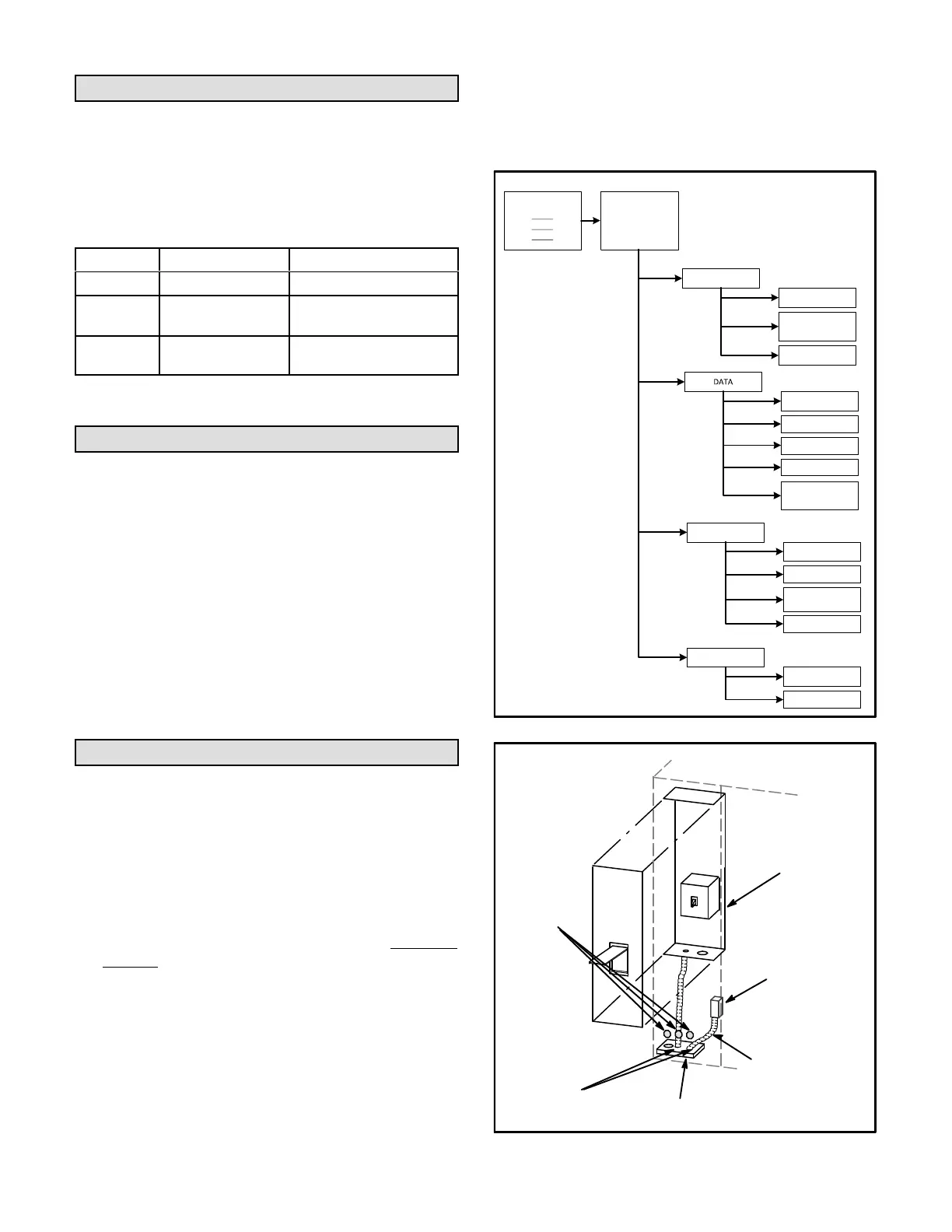
B-New Installations
Once the app is downloaded, refer to the Setup Guide
provided with this unit to pair the app to the unit control
system. Follow the setup wizard prompts to configure the
unit. See figure 13 for the app menu overview. If a mobile
device is unavailable or not pairing, refer to the Unit
Controller Setup Guide for start-up instructions.
Electrical Connections - Power Supply
Route field wiring in conduit between bottom power entry
disconnect. See figure 14. This does not supersede local
codes or authorities having jurisdiction.
Do not apply power or close disconnect switch until
installation is complete. Refer to start-up directions.
Refer closely to unit wiring diagram.
Refer to unit nameplate for minimum circuit ampacity
and maximum fuse size.
1- 230/460/575 volt units are factory wired. For 208V
supply, disconnect the orange wire (230V) at all
control power transformer(s). Reconnect the red
wire (208V). Tape the exposed end of the 230V
orange wire.
2- Route power through the bottom power entry area.
On gas units or units with electric heat, connect
power wiring to TB2. On cooling only units,
connect power to F4. If unit contains an optional
factory-installed circuit breaker or disconnect
switch, connect line voltage to CB10 or S48. See
unit wiring diagram.
3- Connect separate 120v wiring to optional
field-powered GFCI outlet. Route field wiring in
conduit between bottom power entry and GFCI. See
figure 14. For unit-powered GFCI, no additional field
wiring is required.
MOBILE SERVICE APP MENU OVERVIEW
MENU
RTU MENU
SETUP
INSTALL
NETWORK
INTEGRATION
TEST AND BALANCETEST AND BALANCE
ALARM HISTORY
DATA TRENDING
FACTORY
RUNTIMES
SYSTEM DATA /
SENSORS / OUTPUTS
SERVICE
COMPONENT TEST
REPORT
ADVANCED
CONTROL
FIRMWARE UPDATE
SETTINGS
RTU OPTION
INSTALL
FIGURE 13
SIDE ENTRY
KNOCKOUTS
SEAL
WATERTIGHT
RUN FIELD
WIRING IN
FIELD PRO
VIDED CONDUIT
BOTTOM
POWER ENTRY
OPTIONAL
120V GFI
MAKE-UP
BOX
FIGURE 14
FIELD WIRE ROUTING
 Loading...