Page 37
Field-Installed Accessories
When field-installing the following accessories, refer to
the latest online installation instruction.
TABLE 11
Accessory
Instruction #
Economizer 507227-XX
Outdoor Air Damper 506340-XX
Electric Heat 507250-XX
Smoke Detector 506437-XX
Factory Unit Controller Settings
Use the mobile service app to adjust parameters; menu
paths are shown in each table. Refer to the Unit Controller
manual provided with each unit.
Tables 12 through 14 show control options. When
applicable, record field-specific information on the label
located inside the compressor access panel.
When field installing optional kits and accessories, the
Unit Controller must be configured to identify the option
before it will function. Refer to figures 40 and 41 to
determine whether the Unit Controller configuration I.D.
must change. To configure the option, use RTU MENU >
SETUP > INSTALL menu path. Press NEXT until
CONFIGURATION ID 1 or 2 appears depending on the
option installed. Change the appropriate character in the
configuration I.D. For example, when an economizer is
installed using a single enthalpy sensor, change
configuration I.D. 1, the second character, to “S”.
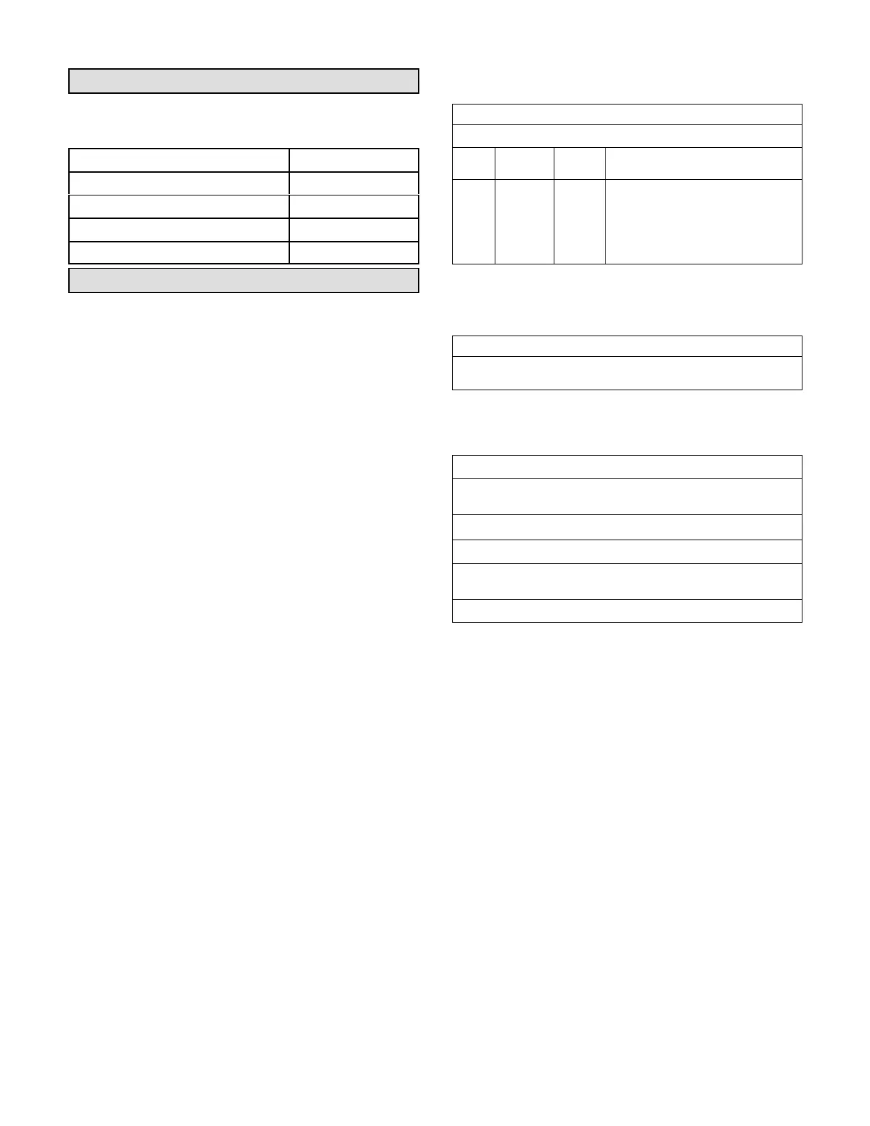
TABLE 12
581024-01
Units With Hot Gas Reheat
RTU Menu > Settings “RTU Options” > Dehumidifier
Para
meter
Factory
Setting
Field
Setting
Description
105 7
Factory Setting 7: Reheat mode en
abled without prerequisite conditions.
Controlled by RH sensor (A91) con
nected to input A55_P298_5 and set
point set at parameter 106 (default
60%).
TABLE 13
581037-01
Units With LonTalk Settings
Use menu RTU Menu > Network Integration > Network Setup Wizard
> Set “LONTALK”
TABLE 14
581038-01
Units With BACnet Settings
RTU Menu > Network Integration > Network Setup Wizard > BACnet
MS/TP > See BACnet MAC Address
BACNET MAC ADDRESS:
Units With Room Sensor, CPC/LSE Gateway Settings
RTU Menu > Network Integration > Network Setup Wizard > SBUS >
Set SBUS Address
LCONN ADDRESS:
 Loading...