Page 31
Service
The unit should be inspected once a year by a qualified
service technician.
CAUTION
Label all wires prior to disconnection when servic
ing controls. Wiring errors can cause improper and
dangerous operation. Verify proper operation after
servicing.
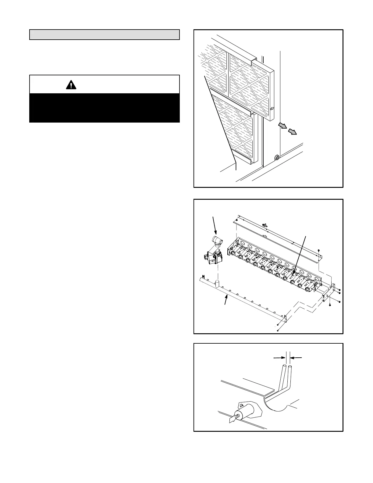
A-Filters
Units are equipped with four 20 X 25 X 2” filters. Filters
should be checked monthly and replaced when
necessary with filters of like kind and size. Take note of
air flow direction marking on filter frame when
reinstalling filters. See figure 29.
NOTE-Filters must be U.L.C. certified or equivalent for
use in Canada.
B-Lubrication
All motors are lubricated at the factory. No further
lubrication is required.
C-Burners (Gas Units)
Periodically examine burner flames for proper
appearance during the heating season. Before each
heating season examine the burners for any deposits or
blockage which may have occurred.
Clean burners as follows:
1- Turn off both electrical power and gas supply to unit.
2- Remove burner compartment access panel.
3- Remove screws securing burner assembly to burner
support and remove assembly. See figure 30. Clean
as necessary.
4- Locate the ignitor under the left burners. Check
ignitor spark gap with appropriately sized twist drills
or feeler gauges. See figure 31.
5- Check the alignment of the ignitor and the sensor as
shown in figure 32 and table 10.
FIGURE 29
REMOVE FILTERS
PULL TO
REMOVE
FILTERS
BURNER BOX ASSEMBLY
240KBTUH SHOWN
FIGURE 30
GAS
MANIFOLD
GAS
VALVE
BURNER ASSEMBLY
SECURED WITH
MULTIPLE SCREWS
FIGURE 31
IGNITOR
SPARK GAP
SHOULD BE 1/8”
(3mm)
 Loading...