Page 32
6- Replace burners and screws securing burner.
7- Replace access panel.
8- Restore electrical power and gas supply. Follow
lighting instructions attached to unit and use
inspection port in access panel to check flame.
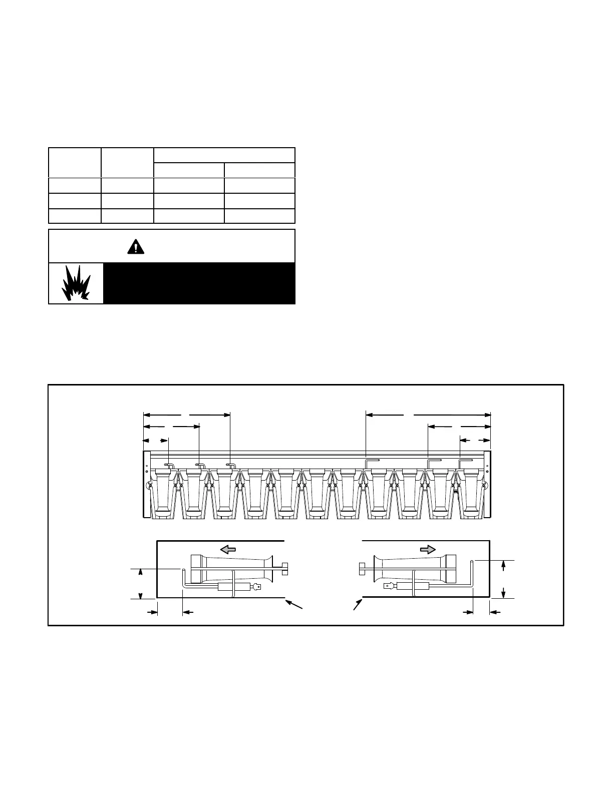
TABLE 10
Dimension
Unit
Btuh Input
Length - in. (mm)
Ignitor Sensor
A 130K 7-3/4 (197) 11 (279)
B 180K 5 (127) 5-1/2 (140)
C 240K 2-1/4 (57) 2-3/4 (70)
WARNING
Danger of explosion. Can cause injury or
death. Do not overtighten main burner
mounting screws. Snug tighten only.
D-Combustion Air Inducer (Gas Units)
A combustion air proving switch checks combustion air
inducer operation before allowing power to the gas
controller. Gas controller will not operate if inducer is
obstructed.
Under normal operating conditions, the combustion air
inducer wheel should be checked and cleaned prior to the
heating season. However, it should be examined
periodically during the heating season to establish an
ideal cleaning schedule. With power supply
disconnected, the condition of the inducer wheel can be
determined by looking through the vent opening.
Clean combustion air inducer as follows:
1- Shut off power supply and gas to unit.
2- Disconnect pressure switch air tubing from
combustion air inducer port.
3- Remove and retain screws securing combustion air
inducer to flue box. Remove vent connector. See
figure 33.
4- Clean inducer wheel blades with a small brush and
wipe off any dust from housing. Clean accumulated
dust from front of flue box cover.
5- Return combustion air inducer motor and vent
connector to original location and secure with
retained screws. It is recommended that the
combustion air inducer gasket be replaced during
reassembly.
6- Clean combustion air inlet louvers on heat access
panel using a small brush.
A
B
C
FIGURE 32
IGNITOR AND SENSOR POSITION
TOP VIEW
SIDE VIEW IGNITOR SIDE VIEW SENSOR
1-3/4”
(45mm)
3/8”
(10mm)
1-3/8”
(35mm)
BURNER BOX
Gas Flow
Gas Flow
13/16”
(21mm)
A
B
C
IGNITOR SENSOR
 Loading...