Page 23
1- The following measurements must be made with a dry
indoor coil. Run blower (G demand) without a cooling
demand. Measure the indoor blower shaft RPM. Air
filters must be in place when measurements are taken.
2- With all access panels in place, measure static
pressure external to unit (from supply to return). Blower
performance data is based on static pressure readings
taken in locations shown in figure 11.
Note - Static pressure readings can vary if not taken where
shown.
3- See table of contents for Blower Data and or Optional
Accessories. Use static pressure and RPM readings to
determine unit CFM.
4- The blower RPM can be adjusted at the motor pulley.
Loosen Allen screw and turn adjustable pulley
clockwise to increase CFM. Turn counterclockwise to
decrease CFM. See figure 12. Do not exceed minimum
and maximum number of pulley turns as shown in table
4.
TABLE 4
MINIMUM AND MAXIMUM PULLEY ADJUSTMENT
Belt Minimum Turns Open
Maximum Turns
Open
A Section No minimum 5
B Section 1* 6
*No minimum number of turns open when B belt is used on
pulleys 6” O.D. or larger.
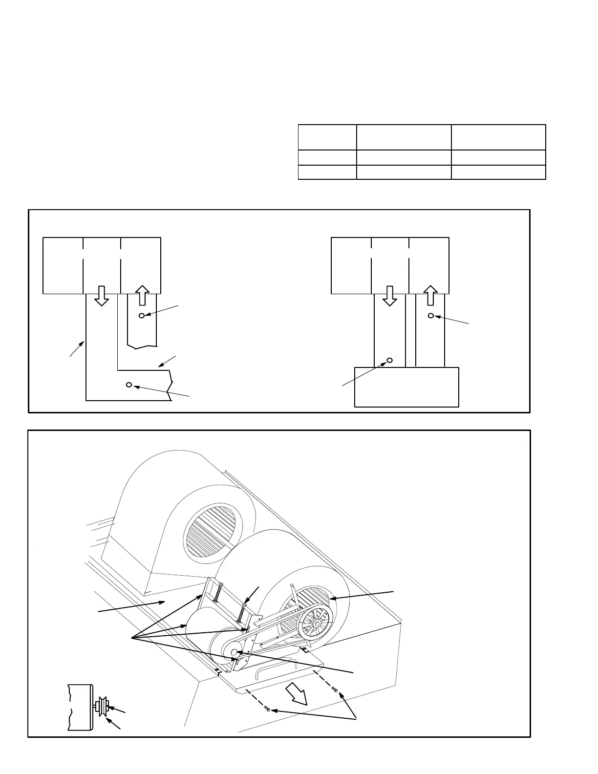
FIGURE 11
LOCATION OF STATIC PRESSURE READINGS
SUPPLY AIR
READING
LOCATION
SUPPLY
RE
TURN
INSTALLATIONS WITH DUCTWORK
SUPPLY
RE
TURN
INSTALLATIONS WITH CEILING DIFFUSERS
MAIN
DUCT RUN
FIRST BRANCH
OFF OF MAIN RUN
DIFFUSER
ROOFTOP UNIT
ROOFTOP UNIT
SUPPLY AIR
READING
LOCATION
RETURN AIR
READING LOCATION
RETURN AIR
READING
LOCATION
BLOWER ASSEMBLY - NO TENSIONER
TO INCREASE BELT TENSION
1-Loosen four screws securing blower motor to
sliding base.
2-Turn adjusting screw to the left, or counter
clockwise, to move the motor downward and
tighten the belt.
3-Tighten four screws.
TO INCREASE CFM
LOOSEN ALLEN SCREW &
TURN PULLEY CLOCKWISE
TO DECREASE CFM
TURN PULLEY
COUNTERCLOCKWISE
FIGURE 12
BLOWER
WHEEL
BLOWER
MOTOR
PULLEY
BLOWER
ASSEMBLY
SLIDING BASE
BELT TENSION
ADJUSTING
SCREW
LOOSEN (4) SCREWS TO
ADJUST BELT TENSION
REMOVE SCREWS TO
SLIDE BLOWER
ASSEMBLY OUT OF UNIT
PULLEY
MOTOR
ALLEN
SCREW
SIDE VIEW
 Loading...
