Page 25
D-GAS HEAT COMPONENTS
See SPECIFICATIONS tables or unit nameplate for Btuh
capacities. Units are equipped with two identical gas heat
sections (gas heat section one and gas heat section two)
see figure 16. Flexible pipe will feed supply gas to the right
side of the heat exchanger. If for service the flexible
connection must broken, hand tighten then turn additional
1/4” with a wrench for metal to metal seal (do not
overtighten).
NOTE - Do not use thread sealing compound on flex pipe
flare connections.
1-Control Box Components
A3, A12, A55
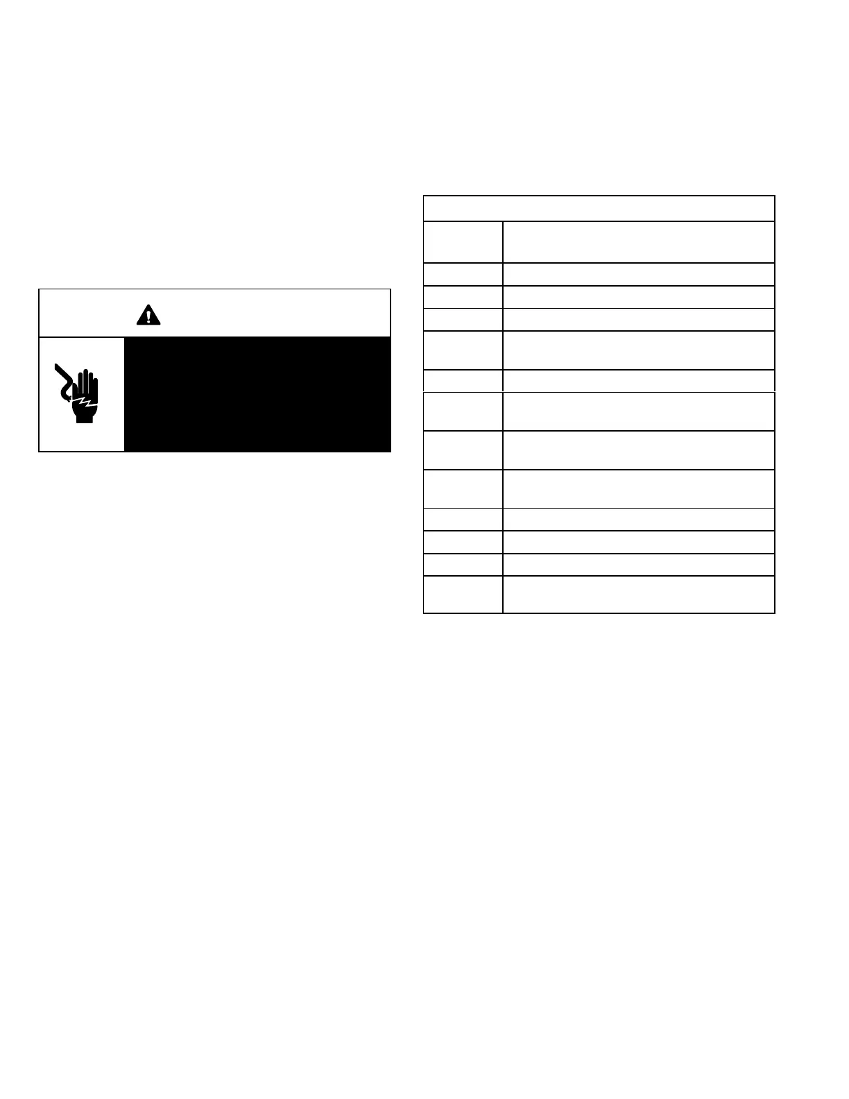
WARNING
Shock hazard. Spark related compo
nents contain high voltage which can
cause personal injury or death. Discon
nect power before servicing. Control is
not field repairable. Unsafe operation
will result. If control is inoperable, sim
ply replace the entire control.
Burner Ignition Control A3, A12
The ignition controls are located in the heat section areas
(figure 16) next to the compressors. The controls are
manufactured UTEC. See table 5 for LED codes.
The ignition control provides three main functions: gas
valve control, ignition and flame sensing. There are three
trials for ignition. Each trial is 10 second long with 30
seconds in between trial. After the third attempt for ignition
the unit will lockout for 60 minutes. After lockout, the ignition
control automatically resets and provides three more
attempts at ignition. Manual reset after lockout requires
breaking and remaking power to the ignition control. See
figure 17 for a normal ignition sequence and figure 18 for
the ignition attempt sequence with retrials (nominal timings
given for simplicity). Specific timings for the ignition controls
are shown in figure 19.
TABLE 5
UTEC
LED
Flashes
Indicates
Slow Flash Control ok, no call for heat
Fast Flash Control ok, call for heat present.
Steady Off Internal control fault or no power
Steady On
Failure
Control internal failure
1 Flash Rollout switch open
2 Flashes
Limit open or lockout from to many tries
during a single heat demand
3 Flashes
Pressure switch open with inducer on/
open during 5 minute inducer off time.
4 Flashes
Ignition lockout from no flame detected or
from too many flame losses.
5 Flashes Flame sensed out of sequence
6 Flashes Pressure switch closed with inducer off
7 Flashes Gas valve relay failure
8 Flashes
Lockout due to too many pressure switch
openings during one heat demand
 Loading...
