-
ing (Fin/Tube Coil)
1 - Using the same thermometer, compare liquid
temperature to outdoor ambient temperature.
Approach Temperature = Liquid temperature (at con-
denser outlet) minus ambient temperature.
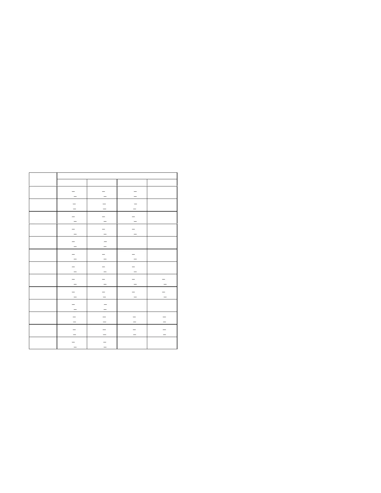
2 - Approach temperature should match values in table
37. An approach temperature greater than value
shown indicates an undercharge. An approach
temperature less than value shown indicates an
overcharge.
3 - The approach method is not valid for grossly over or
undercharged systems. Use tables 24 through 35
as a guide for typical operating pressures.
TABLE 37
APPROACH TEMPERATURES - FIN/TUBE COIL
L Series
Unit
Liquid Temp. Minus Ambient Temp.
1st Stage 2nd Stage 3rd Stage 4th Stage
156H Std.
9°F + 1
(5.0°C +
0.5)
9°F + 1
(5.0°C +
0.5)
11°F + 1
(6.1°C +
0.5)
NA
156H
Reheat
6°F+1
(3.3°C+
0.5)
6°F+1
(3.3°C+
0.5)
11°F+1
(6.1°C+
0.5)
NA
180H Std.
6°F + 1
(3.3°C +
0.5)
6°F + 1
(3.3°C +
0.5)
6°F + 1
(3.3°C +
0.5)
NA
180H
Reheat
4°F + 1
(2.2°C +
0.5)
4°F + 1
(2.2°C +
0.5)
6°F + 1
(3.3°C +
0.5)
NA
180U
5°F + 1
(2.8°C +
0.5)
6.5°F + 1
(3.6°C +
0.5)
NA NA
210H Std.
6°F + 1
(3.3°C +
0.5)
6°F + 1
(3.3°C +
0.5)
7°F + 1
(3.9°C +
0.5)
NA
210H
Reheat
4°F + 1
(2.2°C +
0.5)
4°F + 1
(2.2°C +
0.5)
7°F + 1
(3.9°C +
0.5)
NA
240H Std.
6°F + 1
(3.3°C +0.5)
6°F + 1
(3.3°C +0.5)
7°F + 1
(3.9°C +0.5)
7°F + 1
(3.9°C +0.5)
240H
Reheat
4°F + 1
(2.2°C +0.5)
4°F + 1
(2.2°C+0.5)
8°F + 1
(4.4°C +0.5)
8°F + 1
(4.4°C +0.5)
240U
4°F + 1
(2.2°C +
0.5)
6.5°F + 1
(3.6°C +
0.5)
NA NA
300S Std.
5°F+1
(2.8°C+
0.5)
5°F+1
(2.8°C+
0.5)
8°F+1
(4.4°C+
0.5)
8°F+1
(4.4°C+
0.5)
300S
Reheat
3°F+1
(1.7°C+
0.5)
3°F+1
(1.7°C+
0.5)
8°F+1
(4.4°C+
0.5)
8°F+1
(4.4°C+
0.5)
300U
4°F + 1
(2.2°C +
0.5)
10°F + 1
(5.5°C +
0.5)
NA NA
IV-STARTUP - OPERATION
Refer to startup directions and to the unit wiring diagram
when servicing. See unit nameplate for minimum circuit
ampacity and maximum fuse size.
A-Preliminary and Seasonal Checks
1 - Make sure the unit is installed in accordance with
the installation instructions and applicable codes.
2 -
installed for loose connections. Tighten as required.
Refer to unit diagram located on inside of unit
control box cover.
3 - Check to ensure that refrigerant lines are in good
condition and do not rub against the cabinet or
other refrigerant lines.
4 - Check voltage. Voltage must be within the range
listed on the nameplate. If not, consult power
company and have the voltage corrected before
starting the unit.
5 - Recheck voltage and amp draw with unit running. If
voltage is not within range listed on unit nameplate,
stop unit and consult power company. Refer to unit
nameplate for maximum rated load amps.
6 - Inspect and adjust blower belt (see section on
Blower Compartment - Blower Belt Adjustment).
NOTE-Crankcase heaters must be energized 24 hours
before attempting to start compressor. Set thermostat so
that there is no demand to prevent compressor from cy-
cling. Apply power to unit.
1 -
according to instructions provided with thermostat.
2 - First-stage thermostat demand will energize
compressors 1 and 2 on all standard and high
will energize compressor on all standard and high
First-stage thermostat demand will energize
one compressor from each circuit on ultra high
will energize the remaining two compressors, one in
3 - Units contain three or four refrigerant circuits or
stages.
4 - Each refrigerant circuit is separately charged with
refrigerant. See unit rating plate for correct amount
of charge.
NOTE - Refer to III-CHARGING for proper method
to check refrigerant charge.
 Loading...


