Page 47
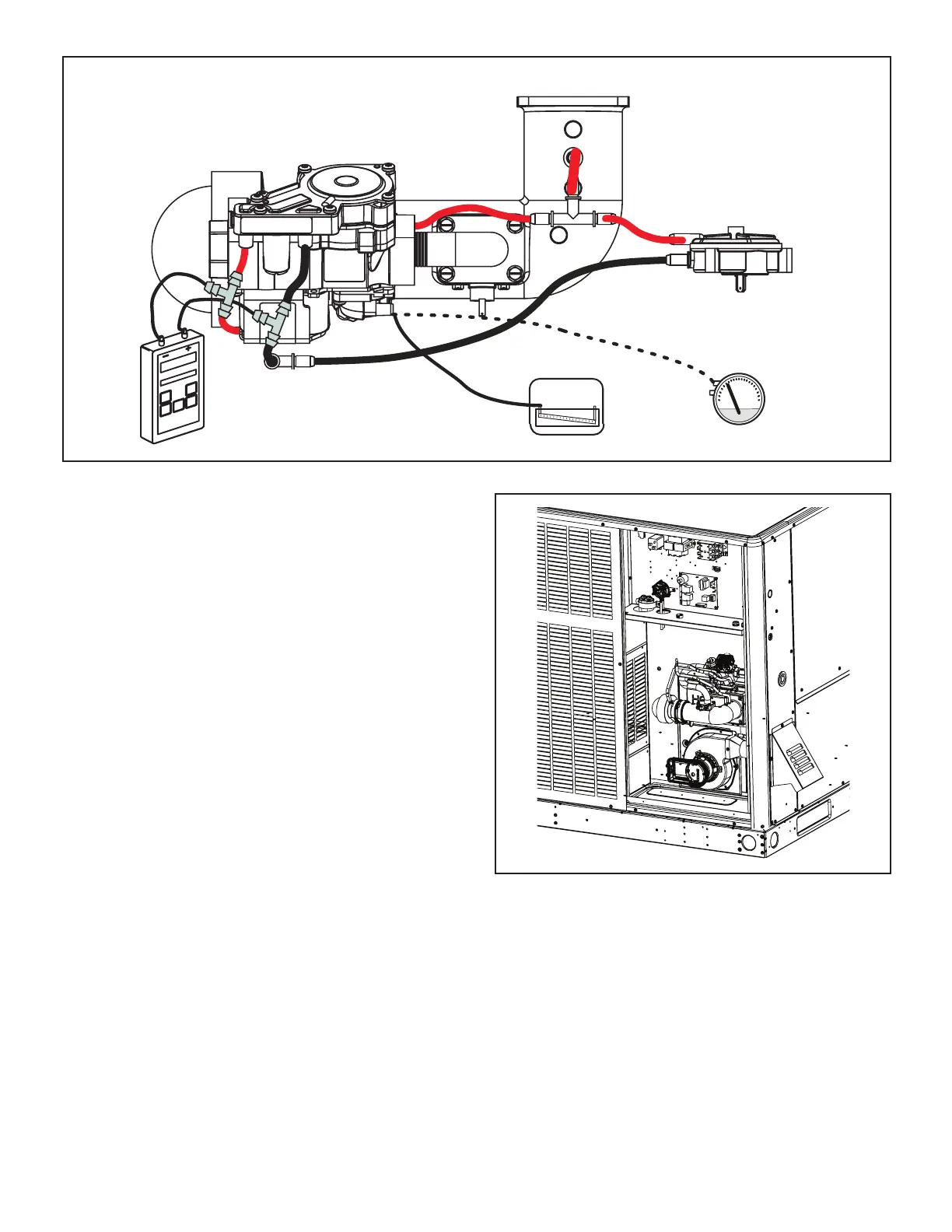
Operating Signal Pressure and Manifold Pressure Measurement
+_
or
High
Low
Signal Pressure
Manifold Pressure
FIGURE 26
Manifold Pressure
A unit’s Manifold Pressure is the product of the Signal
Pressure x the Gas Valve’s Amplication Factor (MP = ∆P
x AF). If the manifold pressure is not within specication,
it will be helpful to determine if it is the Signal Pressure or
the Amplication Factor that is the culprit. The amplica-
tion factor is 4.0 ± 20% (so 3.2 – 4.8). Typical gas valves
that we have encountered during development seem to
range between 3.8 and 4.2.
Condition: Signal Pressure Amplication Factor Man-
ifold Pressure Notes
• Nominal 0.72 4.0 2.9
• Low Amp 0.72 3.8 2.7 Not full AF tolerance range
• High Amp 0.72 4.2 3.0 Not full AF tolerance range
• Low Signal 0.67 4.0 2.7
• High Signal 0.77 4.0 3.1
• Both Low 0.67 3.8 2.6 Not full AF tolerance range
• Both High 0.77 4.2 3.2 Not full AF tolerance range
FIGURE 27. Typical Heating Parts Arrangement
Post-Start Checklist
After the entire control circuit has been energized and the
heating section is operating, make the following checks:
1 - Check for gas leaks, using soapy solution, in the
unit piping as well as the supply piping.
2 - Check the supply gas pressure. It must be within the
limits shown on the rating plate. Supply pressure
should be checked with all gas appliances in the
building at full re. At no time should the standby
gas pressure exceed 13” w.c., nor the operation
pressure drop below 5” w.c. for natural gas units. If
gas pressure is outside these limits, contact the gas
supplier for corrective action.
 Loading...

