Page 14
WARNING
USE COPPER CONDUCTORS ONLY
1 - Disconnect all power supplies.
2 - Remove the air handler access panel.
3 - Route the eld supply wires to the air handler
electrical connection box.
4 - Use UL-listed wire nuts to connect the eld supply
conductors to the unit black and yellow leads, and
the ground wire to ground terminal marked GND.
5 - 5. Replace the air handler access panel.
FIGURE 11. Electrical Connections
(Upow Conguration)
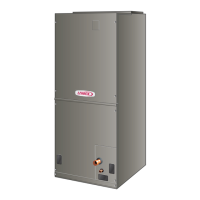
Control Panel Relocation
To avoid the possibility of moisture damage to the control
in some right-hand discharge congurations, the control
panel can be relocated to the end panel as shown in gure
13.
1 - Remove the two screws that secure the control
panel to the cabinet. See gure 11. Slide panel out.
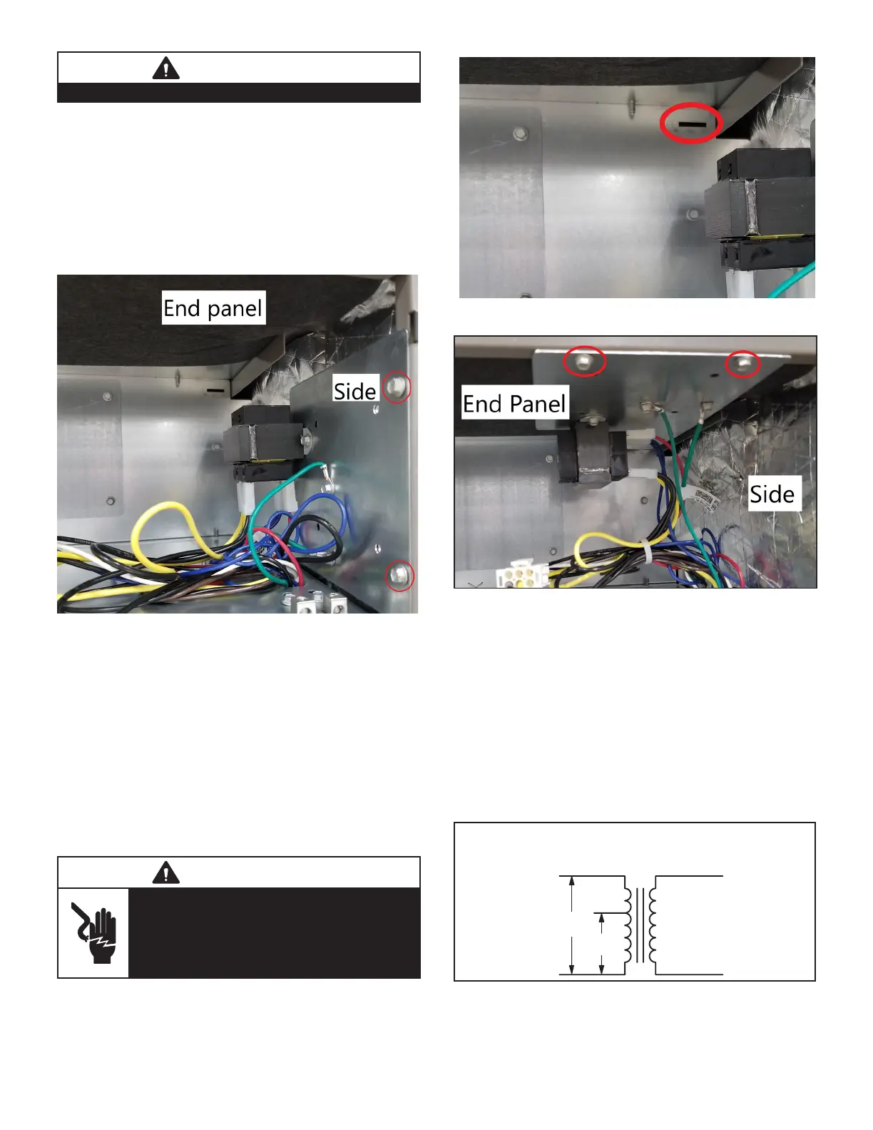
2 - Slide the control panel into the notch on the electric
heat mounting panel (gure 12). Using the screws
removed in Step 1, secure the control panel to the
end panel, as shown in gure 13.
WARNING
Electrically ground air handler. Connect
ground wire to ground terminal marked
“GND”.
Failure to do so can result in death or
electrical shock.
FIGURE 12. Notch for Control Panel Relocation
FIGURE 13. Control Panel Relocated to End Panel
(Horizontal-Right Conguration)
208 VOLT CONVERSION
1 - Disconnect all power supplies.
2 - Remove the air handler access panel.
3 - Using the wiring diagram located on the unit access
panel as a reference, move the 2 connected black
transformer leads from the 240 volt terminal on
the transformer to the 208 volt terminal on the
transformer.
208 / 240 VOLT TRANSFORMER
PRIMARY SECONDARY
240 Volts
208 Volts
FIGURE 14. Converting Unit from 240VAC to 208VAC

 Loading...