Page 13
5 - If necessary, run the condensate line into a condensate
pump to meet drain line slope requirements. The
pump must be rated for use with condensing furnaces.
Protect the condensate discharge line from the pump
to the outside to avoid freezing.
6 - Continue with exhaust, condensate and intake piping
installation according to instructions.
Return Air -- Horizontal Applications
Return air may be brought in only through the end of a
furnace installed in the horizontal position. The furnace is
equipped with a removable bottom panel to facilitate in-
stallation. See gure 15.
*Gas connector may be
used for Canadian
able by local authority
having jurisdiction.
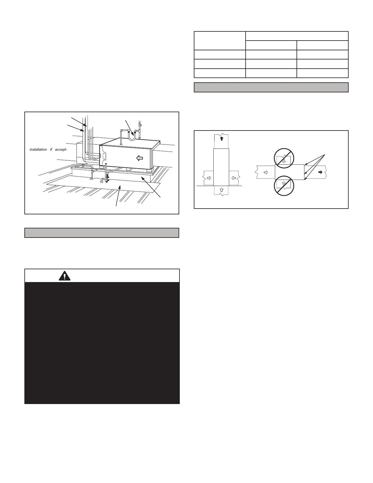
RAISED
PLATFORM
SERVICE PLATFORM
INTAKE PIPE
EXHAUST PIPE
FIGURE 19
Filters
This unit is not equipped with a lter or rack. A eld-pro-
vided high velocity rated lter is required for the unit to
operate properly. Table 1 lists recommended lter sizes. A
lter must be in place whenever the unit is operating.
IMPORTANT
If a high eciency lter is being installed as part of this
system to ensure better indoor air quality, the lter must
be properly sized. High eciency lters have a higher
static pressure drop than standard eciency glass/foam
lters. If the pressure drop is too great, system capacity
and performance may be reduced.
The pressure drop may also cause the limit to trip more
frequently during the winter and the indoor coil to freeze
in the summer, resulting in an increase in the number of
service calls.
Before using any lter with this system, check the
specications provided by the lter manufacturer against
the data given in the appropriate Lennox Product
Specications bulletin. Additional information is provided
in Service and Application Note ACC002
(August 2000).
TABLE 1
Furnace
Cabinet Width
Filter Size
Side Return Bottom Return
17-1/2” 16 X 25 X 1 (1) 16 X 25 X 1 (1)
21” 16 X 25 X 1 (1) 20 X 25 X 1 (1)
24-1/2” 16 X 25 X 1 (2) 24 X 25 X 1 (1)
Duct System
Use industry-approved standards to size and install the
supply and return air duct system. Refer to ACCA Manual
D. This will result in a quiet and low-static system that has
uniform air distribution. See below for proper duct instal-
lation.
HORIZONTAL UNIT
SUPPLY
AIR
SUPPLY
AIR
Install self tapping screws
to seal any potential air
leaks
UPFLOW UNIT
FIGURE 20
NOTE - This furnace is not certied for operation in heat-
ing mode (indoor blower operating at selected heating
speed) with an external static pressure which exceeds 0.8
inches w.c. Operation at these conditions may result in
improper limit operation.
Supply Air Plenum
If the furnace is installed without a cooling coil, a remov-
able access panel should be installed in the supply air
duct. The access panel should be large enough to per-
mit inspection of the heat exchanger. The furnace access
panel must always be in place when the furnace is oper-
ating and it must not allow leaks. For horizontal only, in-
stall self tapping screws in the three evaporator coil screw
holes made for horizontal applications to seal the top cap
to the vestibule panel.
Return Air Plenum
NOTE - Return air must not be drawn from a room
where this furnace, or any other gas-fueled appliance
(i.e., water heater), or carbon monoxide-producing de-
vice (i.e., wood replace) is installed.
When return air is drawn from a room, a negative pressure
is created in the room. If a gas appliance is operating in
a room with negative pressure, the ue products can be
pulled back down the vent pipe and into the room. This
reverse ow of the ue gas may result in incomplete com-
bustion and the formation of carbon monoxide gas. This
raw gas or toxic fumes might then be distributed through-
out the house by the furnace duct system.
 Loading...