Page 2
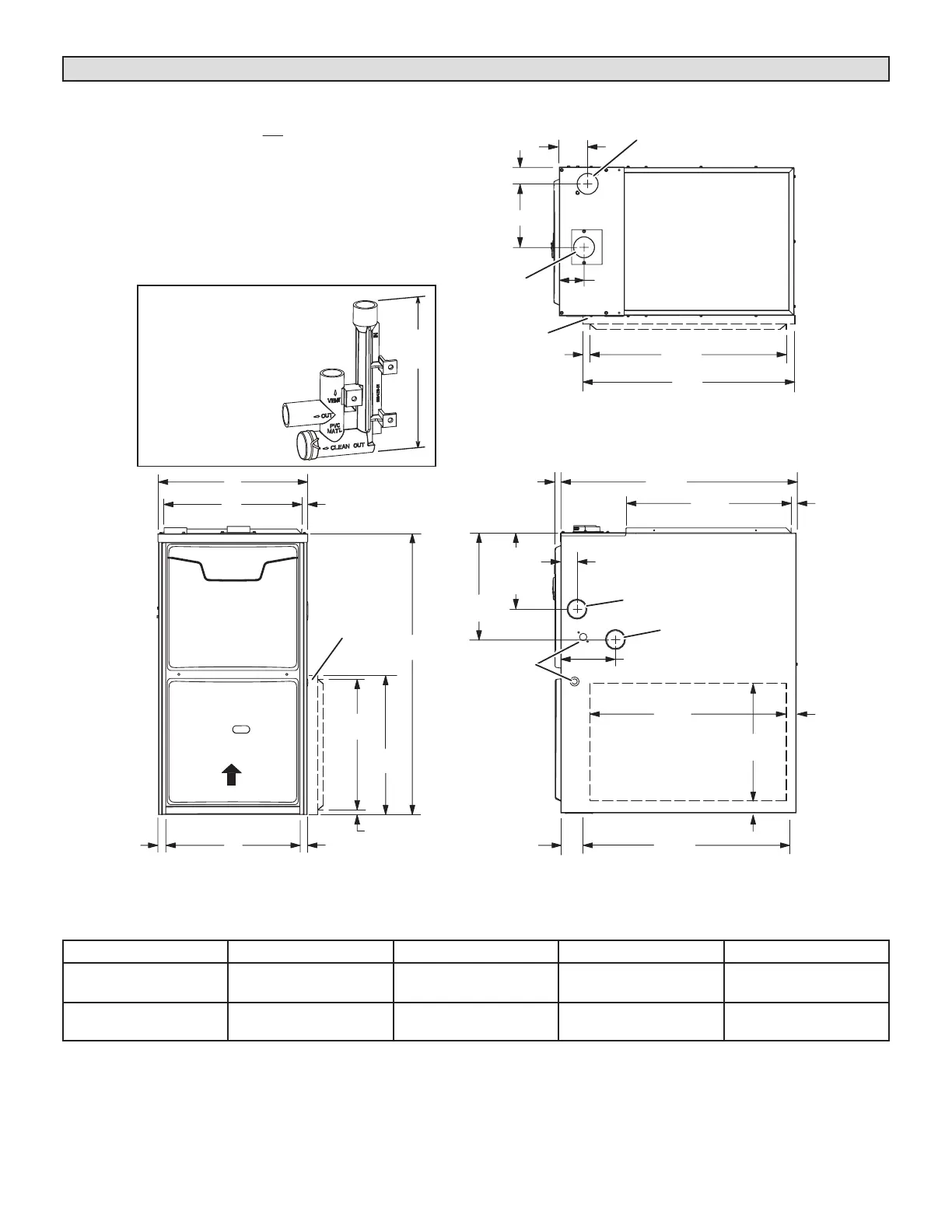
Unit Dimensions - inches (mm)
Model A B C D
ML296UH045XV36B
ML296UH070XV36B
17−1/2 in 446 mm 16−3/8 in 416 mm 16 in 406 mm 7−5/8 in 194 mm
ML296UH090XV48C
ML296UH110XV60C
21 in 533 mm 19−7/8 in 505 mm 19−1/2 in 495 mm 9−3/8 in 238 mm
6-9/16 (167)
Left
9 (229)
Right
23
(584)
(19)
3/4
(19)
1
Bottom Return
Air Opening
GAS PIPING INLET
(Either Side)
Side Return
Air Opening
(Either Side)
1
Bottom Return
Air Opening
EXHAUST AIR
OUTLET
ELECTRICAL
INLET
(Either Side)
SUPPLY AIR
OPENING
FRONT VIEW SIDE VIEW
TOP VIEW
A
B
9/16 (14)
C
3/4
27-3/4
(705)
19-7/16
(494)
23-1/2
(597)
1-1/2
(38)
6-1/2 (165)
(Either Side)
33
(838)
3-3/8
(86)
1-15/16 (49)
14
(356)
9/16
(14)
12-5/8 (321)
(Either Side)
2
OPTIONAL
SIDE RETURN
AIR FILTER KIT
(Either Side)
16
(406)
14-3/4
(375)
2
OPTIONAL
SIDE RETURN
AIR FILTER KIT
(Either Side)
5/8
(16)
1
3-1/4
(83)
23-3/4
(603)
25
(635)
D
1 (25)
Front Panel
COMBUSTION
AIR INTAKE
2 (51)
(Either Side)
2 (51)
CONDENSATE
TRAP CONNECTION
(Either Side)
2
Optional Side Return Air Filter Kit is not for use
with the Optional Return Air Base.
1
2-7/8
(73)
AIR FLOW
Flue Condensate Trap Assembly
Furnished for external
field installation
on either side of unit.
(See installation instructions
for additional
information.)
7
(178)
NOTE - 60C size units that require air volumes over
1800 cfm must have one of the following:
1. Single side return air and Optional Return Air Base
with transition that must accommodate required
20 x 25 x 1 inch (508 x 635 x 25 mm) air filter to
maintain proper velocity.
2. Bottom return air.
3. Return air from both sides.
4. Bottom and one side return air.
See Blower Performance Tables for additional information.
 Loading...