Page 23
Intake Piping
The ML296UHV furnace may be installed in either direct
vent or non-direct vent applications. In non-direct vent ap-
plications, when intake air will be drawn into the furnace
from the surrounding space, the indoor air quality must be
considered and guidelines listed in Combustion, Dilution
and Ventilation Air section must be followed.
Follow the next two steps when installing the unit in Direct
Vent applications, where combustion air is taken from out-
doors and ue gases are discharged outdoors. The pro-
vided air intake screen must not be used in direct vent
applications (outdoors).
1 - Use transition solvent cement or a sheet metal screw
to secure the intake pipe to the inlet air connector.
2 - Route piping to outside of structure. Continue with
installation following instructions given in general
guidelines for piping terminations and intake and
exhaust piping terminations for direct vent sections.
Refer to table 5 for pipe sizes.
TYPICAL AIR INTAKE PIPE CONNECTIONS
UPFLOW NON−DIRECT
VENT APPLICATIONS
INTAKE
DEBRIS
SCREEN
(Provided)
NOTE - Debris screen and elbow may be rotated, so that
screen may be positioned to face forward or to either side.
FIGURE 27
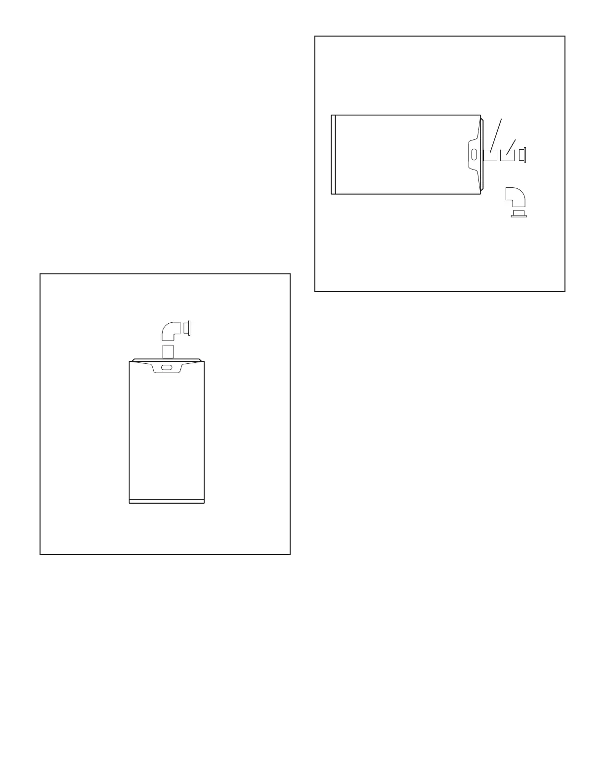
TYPICAL AIR INTAKE PIPE CONNECTIONS
HORIZONTAL NON−DIRECT VENT APPLICATIONS
(Horizontal Right−Hand Air Discharge Application Shown)
INTAKE
DEBRIS
SCREEN
(Provided)
OR
NOTE - Debris screen may be positioned straight out
(preferred) or with an elbow rotated to face down.
coupling
PVC pipe
FIGURE 28
Follow the next two steps when installing the unit in Non-
Direct Vent applications where combustion air is taken
from indoors or ventilated attic or crawlspace and ue
gases are discharged outdoors.
1 - Use eld-provided materials and the factory-
provided air intake screen to route the intake piping
as shown in gure 27 or 28. Maintain a minimum
clearance of 3” (76mm) around the air intake
opening. The air intake opening (with the protective
screen) should always be directed forward or to
either side in the upow position, and either straight
out or downward in the horizontal position.
The air intake piping must not terminate too close
to the ooring or a platform. Ensure that the intake
air inlet will not be obstructed by loose insulation
or other items that may clog the debris screen.
2 - If intake air is drawn from a ventilated attic (gure
29) or ventilated crawlspace (gure 30) the exhaust
vent length must not exceed those listed in table 6. If
3” diameter pipe is used, reduce to 2” diameter pipe
at the termination point to accommodate the debris
screen.
3 - Use a sheet metal screw to secure the intake pipe to
the connector, if desired.
 Loading...