Page 33
6 - If unit will be started immediately upon completion
of installation, prime trap per procedure outlined in Unit
Start-Up section.
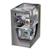
(Unit shownin upflow position withremote trap)
*5’ max.
To Drain
PVC PipeOnly
FieldProvidedVent
Min.1” Above Condensate
Drain
Connection
1”
Min.
Trap CanBeInstalleda
Maximum 5’ From Furnac
e
2” Max.
CONDENSATE TRAP LOCATIONS
*Piping from furnace must slope down a
minimum 1/4” per ft. toward trap
FIGURE 48
Condensate line must slope downward away from the trap
to drain. If drain level is above condensate trap, conden-
sate pump must be used. Condensate drain line should
be routed within the conditioned space to avoid freezing of
condensate and blockage of drain line. If this is not possi-
ble, a heat cable kit may be used on the condensate trap
and line. Heating cable kit is available from Lennox in var-
ious lengths; 6 ft. (1.8m) - kit no. 26K68; 24 ft. (7.3m) - kit
no. 26K69; and 50 ft. (15.2m) - kit no. 26K70.
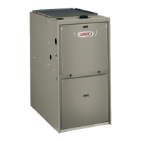
Coil Using A Separate Drain
Condensate
Drain
Connection
Field Provided Vent
(1” min. 2” max. above
condensate connection)
Evaporator drain
line required
(Trap at coil is optional)
FIGURE 49
Furnace with Evaporator Coil Using a Separate Drain
(Unit shown in horizontal left-hand discharge position)
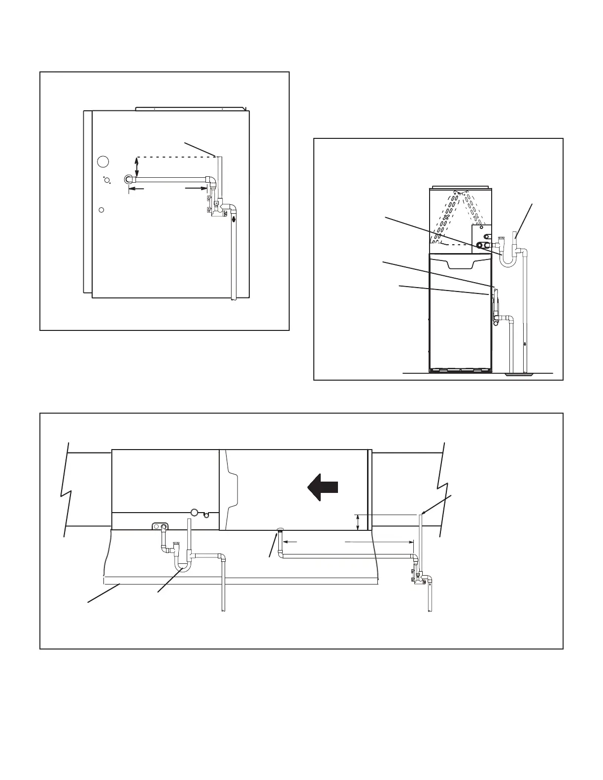
.
5’ max.
PVC Pipe Only
4”min
5”max
Evaporator
Coil
Drain
Pan
Condensate
DrainConnection
Field Provided Vent
(4” min. to 5” max. above
condensate connection)
Piping from furnace and evaporator coil must slope down a minimum 1/4” per ft. toward trap
(Trap at coil is optional)
FIGURE 50
 Loading...