14
NOTE: DIAGRAMS & ILLUSTRATIONS ARE NOT TO SCALE.
LENNOX HEARTH PRODUCTS • MERIT PLUS
®
DIRECT VENT GAS FIREPLACES (MPDP35/40) • INSTALLATION INSTRUCTIONS
Select Venting System
(Horizontal or Vertical)
With the appliance secured in framing, determine
vent routing and identify the exterior termina-
tion location. The following sections describe
vertical (roof) and horizontal (exterior wall) vent
applications. Refer to the section relating to your
installation. See Pages 36 and 37 for a list of
approved venting components.
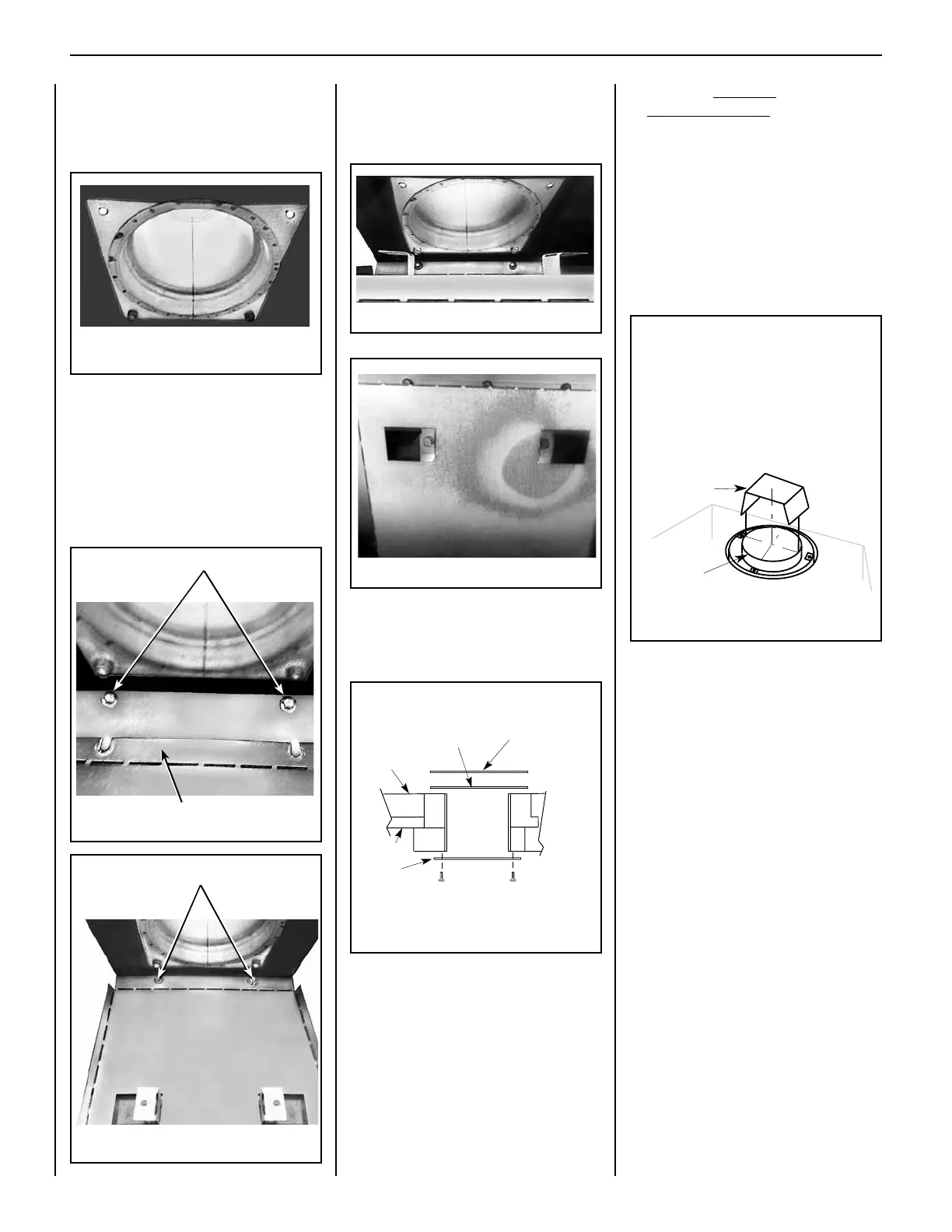
Vent Restrictor Installation in Top Vent
Systems
Note: When top venting the fireplace, the top
vent flue restrictor MUST be installed.
Figure 23
IF TOP VENT VERTICAL VENT LENGTH
IS 8 FEET OR LONGER:
Before attaching the first piece of venting
pipe, install the U-shaped vent restrictor
into the top vent collar from outside the
unit (Figure 25). The U-shaped vent
restrictor is held in place by friction.
Note: An elbow may NOT be directly
attached to the fireplace top vent col-
lar. A minimum of 1 ft. of vertical vent
pipe must be attached to the top vent
collar before installing any elbow.
When top venting, remove the outer top
knockout and gasket from outside the unit
(Figure 24).
U-shaped
Vent Restrictor
Appliance Top
Vent OUtlet
Inner
Fireplace
Collar
Installation of the U-shaped vent restrictor
is required in top vent applications with vent
runs over 8 feet.
Install the vent restrictor from outside the
unit in the inner fireplace collar of the top
vent outlet, oriented as shown below.
U-SHAPED VENT RESTRICTOR INSTALLATION
(TOP VENT)
Figure 25
Figure 19
1. Remove the 2 top front screws and loosen
the 2 top rear screws of the rear solid cover
plate (Figures 19 and 20).
2. Install the top vent flue restrictor by
sliding the two notches in the top vent flue
restrictor (Figure 20) under and behind the
two screws loosened in the previous step,
and then tighten the screws (Figure 21).
3. Bend the top vent flue restrictor FORWARD
and UP (Figure 22), and secure with the
other 2 previously removed screws (Figure
23).
Loosen screws.
Tighten screws.
Top Vent Flue Restrictor
KNOCKOUT
GASKET
FIREBOX TOP
CABINET TOP
VENT
COVER PLATE
TOP VENT
TOP VENT SEAL AND COVER PLATE REMOVAL
WHEN USING THE TOP VENT
COVER PLATE
SECURING SCREWS
CROSS SECTION
(INSIDE UNIT)
(OUTSIDE UNIT)
Figure 24
Figure 21
Figure 22
Figure 20
 Loading...