28
NOTE: DIAGRAMS & ILLUSTRATIONS ARE NOT TO SCALE.
LENNOX HEARTH PRODUCTS • MERIT PLUS
®
DIRECT VENT GAS FIREPLACES (MPDP35/40) • INSTALLATION INSTRUCTIONS
Turn on gas supply and test for gas leaks, us-
ing a gas leak test solution (also referred to as
bubble leak solution).
Note: Using a soapy water solution is an effec-
tive leak test solution but it is not recommended,
because the soap residue that is left on the
pipes/fittings can result in corrosion over time.
A. Light the appliance (refer to the lighting
instructions label in the control compartment
or in the Care and Operation Instructions
manual).
B. Brush all joints and connections with the gas
leak test solution to check for leaks. If bubbles
are formed, or gas odor is detected, turn the
receiver or remote control to the “OFF” position.
Either tighten or refasten the leaking connection,
then retest as described above.
C. When the gas lines are tested and leak free,
be sure to rinse off the leak testing solution.
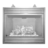
Step 7. CONNECTING GAS LINE
Make gas line connections. All codes require a
shut-off valve mounted in the supply line. Figure
52 illustrates two methods for connecting the
gas supply. The flex-line method is acceptable
in the U.S., however, Canadian requirements
vary depending on locality. Installation must
be in compliance with local codes.
A sediment trap is recommended in the gas
piping within the home to prevent moisture
and debris in the line from damaging the valve.
These appliances are equipped with a gas flex
line for use (where permitted) in connecting the
unit to the gas line. A gas flex line is provided
to aid in attaching the direct vent appliance to
the gas supply. The gas flex line can only be
used where local codes permit. Refer to Figure
52 for flex line description. The flex line is rated
for both natural and propane gas. A manual
shut off valve is also provided with the flex line.
The gas control valve is located in the lower
control compartment.
To access the valve, open the lower control
compartment door by pushing in the right top
corner of the door (the door is hinged at the
bottom). Remove the bottom compartment door
by sliding the hinge pin, located at the door’s
left side, to the right until it disengages from the
left corner post hole. Pull the door diagonally
to the left, away from the fireplace.
Secure all joints tightly using appropriate
tools and sealing compounds (ensure propane
resistant compounds are used in propane
applications). Optional: Seal around the gas
line to prevent cold air leakage. Gas line holes
and other openings can be caulked or stuffed
with unfaced fiberglass insulation.
WARNING
Never use an open flame to
check for leaks.
TEST ALL CONNECTIONS FOR GAS LEAKS
(FACTORY AND FIELD):
Step 8. VERIFYING APPLIANCE
OPERATION
With gas line installed, run initial system
checkout before closing up the front of the
unit. Follow the lighting instructions provided
in the Care and Operation Instructions.
Note: Lighting Instructions are also found on
the literature tag tied to the gas piping next
to the gas valve. To access the tag, open the
lower control compartment door by pushing
in the right top corner of the door (the door
is hinged at the bottom). Remove the bottom
compartment door by sliding the hinge pin,
located at the door’s left side, to the right until
it disengages from the left corner post hole.
When first lighting the appliance, it will take a
few minutes for the line to purge itself of air.
Once purging is complete, the pilot and burner
will light and operate as indicated in the instruc-
tion manual.
Subsequent lighting of the appliance will not
require such purging. Inspect the pilot flame
(remove logs, if necessary, handling carefully).
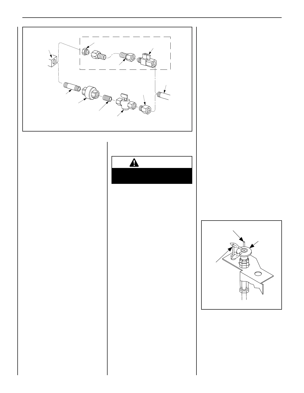
Electronic Appliance Checkout
To light the burner, turn on the remote control.
Ensure the igniter lights the pilot. The pilot
flame should engulf the flame rod as shown
in Figure 53.
Figure 52: Gas Connection
Gas
Stub
1/2" x 3/8" Flare
Shut-Off Valve
3/8" Flex Tubing
3/8" NPT x 3/8"
Flare Fitting
3/8" Nipple
3/8" Union
3/8" Close Nipple
3/8" Shut-Off Valve
1/2" x 3/8"
Reducer
Gas
Valve
Optional Gas Flex Line Connector
Pilot
Hood
Sensor
Ignitor
Figure 53
Igniter
Flame Rod
(sensor)
Pilot Hood
 Loading...