33
NOTE: DIAGRAMS & ILLUSTRATIONS ARE NOT TO SCALE.
LENNOX HEARTH PRODUCTS • MERIT PLUS
®
DIRECT VENT GAS FIREPLACES (MPDP35/40) • INSTALLATION INSTRUCTIONS
WARNINGS
• Air shutter adjustment should
only be performed by a quali-
fied professional service tech-
nician.
• Ensure front glass panel are
in place and sealed during
adjustment.
CAUTIONS
• Soot will be produced if the
air shutter is closed too much.
Any damage due to sooting,
resulting from improperly
setting the air shutter, is not
covered under the warranty.
• The air shutter door and
nearby appliance surfaces
are hot. Exercise caution to
avoid injury while adjusting
flame appearance.
Figure 61
sledoM
saG
epyT
RIAYROTCAF
RETTUHS
GNITTES
)mm(sehcni
MPDP35
Nat.
1/16 (1.6)
.porP 61/3 )67.4(
.taN 8/1 )2.3(
.porP
MPDP40
3/8 (9.6)
Burner Flame Adjustments
Adjustment Rod Up
(Fully Open Position)
Air Shutter
Burner Tube
Adjusting Set Screw
Adjustment Rod Down
(minimum air
opening position)
Adjustment Rod Down
(fully open position)
Adjustment Rod Up
(minimum air
opening position)
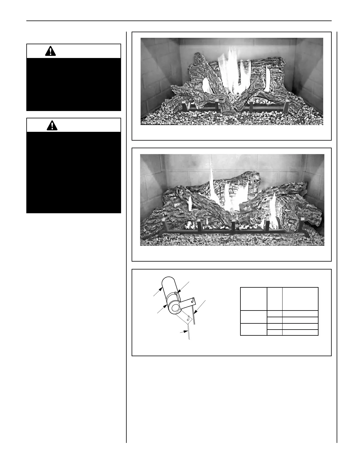
1. Refer to Figures 59 and 60 for proper flame
appearance. To adjust the flame, rotate the
adjustment rod toward the back or toward
the front of the fireplace (rod located in the
lower control area). Position the air shutter
to the factory setting as shown in the table
in Figure 61.
2. Light the appliance (follow lighting procedure
on lighting label in control compartment or
in the Care and Operation Instructions).
3. Allow the burner to operate for at least 15
minutes while observing the flame continu-
ously to ensure that the proper flame ap-
pearance has been achieved. If the following
conditions are present, adjust accordingly.
• If flame appears weak or sooty, adjust
the air shutter, incrementally, to a more
open position until the proper flame
appearance is achieved.
• If flame remains blue, adjust the air
shutter, incrementally, to a more closed
position until the proper flame appear-
ance is achieved.
4. When satisfied that the burner flame appear-
ance is normal, reinstall the lower control
compartment door, then proceed to finish
the installation.
Figure 59 - Burner Flame Appearance, Model MPDP35
Figure 60 - Burner Flame Appearance, Model MPDP40
 Loading...