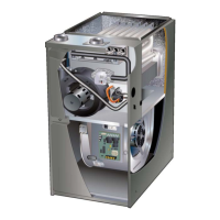
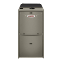
Do you have a question about the Lennox ML193UH045P36B and is the answer not in the manual?
Critical safety warnings for electrical shock, installation, and sharp edges.
Diagram showing major components of the ML193UH unit.
Details of transformer, interlock switch, ignition control, and terminal designations.
Critical safety warnings and ESD precautions for servicing controls.
Fan control adjustments, terminal designations, and system operation overview.
Table of diagnostic codes and sequence of operation timing diagram.
Electronic ignition process, safety warnings, and terminal designations.
Table of diagnostic codes and terminal designations for troubleshooting.
Wiring diagram for the integrated control and its electronic ignition sequence.
Details on ignitor, flame sensor, rollout switches, and burner box assembly diagram.
Procedures and tables for checking ignitor resistance and voltage.
Info on limit control, heat exchanger, burners, orifices, and gas valve.
Details on inducer, header box, pressure switch, and orifice sizes.
Procedures for measuring pressure differential and accessing blower components.
Cautions for confined spaces and general guidelines for vent terminations, including important notes.
Diagrams showing condensate trap locations and field-provided drain components.
Detailed diagrams for trap and drain assemblies using 3/4" PVC piping.




 Loading...