20
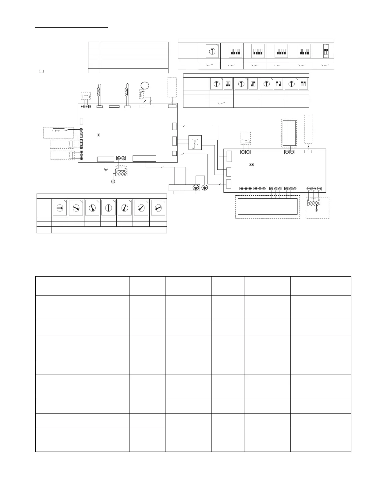
36-60K Wiring Diagram
3.6. Wiring Guide
Table 1. Single Zone Mini-Split Wiring Guide
Systems
System
Capacity
System Voltage
Number of
Conductors
Wire Type Wire Gauge
Indoor to Outdoor Wiring
(Communication/Power)
1, 2, 3 and GND
18K 208/230 VAC 4 Stranded
16AWG*4 Stranded,
unshielded
Outdoor to Main Power
L1, L2 and GND
18K 208/230 VAC 3 Stranded
MCA: 18A
14AWG*3
Indoor to Outdoor Wiring
(Communication/Power)
1, 2, 3 and GND
24K 208/230 VAC 4 Stranded
16AWG*4 Stranded,
unshielded
Outdoor to Main Power
L1, L2 and GND
24K 208/230 VAC 3 Stranded
MCA: 20A
12AWG*3
Indoor to Outdoor Wiring
(Power only)
L1, L2 and GND
36K 208/230 VAC 3 Stranded
16AWG*3 Stranded,
unshielded
Indoor to Outdoor Wiring
(Communication only) (S1, S2 and GND)
36K 208/230 VAC 3 Stranded (shielded) 24AWG*3
Outdoor to Main Power
L1, L2 and GND
48K 208/230 VAC 3 Stranded
MCA: 30A
10AWG*3
Indoor to Outdoor Wiring
(Power only)
L1, L2 and GND
48K 208/230 VAC 3 Stranded
16AWG*3 Stranded,
unshielded
INDOOR UNIT
MAINBOARD
0
8
4
1
2
3
5
6
7
C
9
A
B
D
E
F
0
8
4
1
2
3
5
6
7
C
9
A
B
D
E
F
0
8
4
1
2
3
5
6
7
C
9
A
B
D
E
F
0
8
4
1
2
3
5
6
7
C
9
A
B
D
E
F
0
8
4
1
2
3
5
6
7
C
9
A
B
D
E
F
0
8
4
1
2
3
5
6
7
C
9
A
B
D
E
F
0
8
4
1
2
3
5
6
7
C
9
A
B
D
E
F
ENC1
4
5
7
8
9
A
B
CAPACITY
CODE
≤
53
54~71
72~90
91~105
106~140
141~160
≥
161
FACTORY
ACCORDING TO RELATED MODEL.
ACCORDING TO RELATED MODEL.
FOR SETTING POWER(DC
MOTOR MODEL ONLY
)
Y/G
CN18
CN23
ALARM
CN33
WORK
6
CN10
CN5
WATER LEVEL
CN46
T1
ECM
CN15
M
4(3)
3
CN34
CN43
UVLED
OUTPUT
BLUE
RED
RED
TRANS
CN22
RED
0
8
4
1
2
3
5
6
7
C
9
A
B
D
E
F
1
2
ON
0
8
4
1
2
3
5
6
7
C
9
A
B
D
E
F
1
2
ON
0
8
4
1
2
3
5
6
7
C
9
A
B
D
E
F
1
2
ON
0
8
4
1
2
3
5
6
7
C
9
A
B
D
E
F
1
2
ON
S1+S2
0~F
0~F
0~F
0~F
NETADDRESS
CODE
0~15
16~31
32~47
48~63
FACTORY
FOR SETTING NETADDRESS
CN9
NOTE2:
1.The other switches should be set as
"Off" state from factory.
2.The specific use of the switches please
reference to the manual of application.
J1
CN29
T2
CN12
3
HEATER
2
CN11
0
8
4
1
2
3
5
6
7
C
9
A
B
D
E
F
0~F
ON~OFF
ON~OFF
ON~OFF
CODE
FACTORY
1
2
3
ON
4
SW1
1
2
3
ON
4
SW2
1
2
3
ON
4
SW3
S3
ON~OFF
1
2
3
ON
4
SW4
1
2
ON
S4
SETTING
CODE
PART NAME
ECM INDOOR ECM MOTOR
T1
T2
T2A
T2B
INDOOR COIL INLET TEMP.SENSOR
ROOM TEMP.SENSOR
COIL TEMP.SENSOR
INDOOR COIL OUTLET TEMP.SENSOR
L1
L2
RED
BLACK
TO OUTDOOR UNIT
OR POWER
2
NL
L and N :230VAC
SWITCH
Output:5VDC
Output:24VAC
Output:5VDC
Output:5VDC
Output:220VAC
Output:12VDC
Output:24VAC
Output:15VDC
Output:220VAC
Output:24VAC
JR1
CN5
CN4
CN1
CN2
ON/OFF
Remote
Control
CN6
24V THERMOSTAT
CN9 CN10
CN11
CN7
TO THE WIRE
CONTROLLER
CN14
4
485 PORT
CN3
E Y X
To CCM
Comm.Bus
Output:24VAC
Output:24VAC
Output:+15VDC
Output:+12VDC
Output:+15VDC
Output:+12VDC
Output:+5VDC
Output:24VAC
Output:24VAC
Output:24VAC
Output:24VAC
NOTE1:
1.The parts with dotted line indicates
optional features.
2.Remove the short connector of JR1
when you use the "on-off" function.
3.Remove the short connector of J1
when you use the "WATER LEVEL
SWITCH" function.
4. This symbol indicates the element
is optional, the actual shape shall prevail.
3.The CN5/CN23/CN33 connect to left and right terminals.
Y/G
DRY CONTACT
DRY CONTACT
ON~OFF
SETTING
T2B
T2A
CN6
CN21
Output:5VDC
2
2
Output:12VDC
S1 S2
CN20
COMMUNICATION
TO OUTDOOR UNIT
W1
DH
R
C
L
G
Y1
Y/Y2
B
W
W2
E/AUX
 Loading...