52
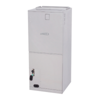
8.6. Single-Zone Piping Limitations
OUTDOOR UNIT
OUTDOOR UNIT
INDOOR UNIT
INDOOR UNIT
Maximum Line Set
Length
Maximum Line Set
Length
Maximum
Elevation -
Outdooor
Unit BELOW
Indoor Unit
Maximum
Elevation -
Outdooor
Unit ABOVE
Indoor Unit
Minimum Line Set
Length - 10 ft. (3m)
Minimum Line Set
Length - 10 ft. (3m)
Outside Unit BELOW Indoor Unit Outside Unit ABOVE Indoor Unit
Do not allow for excess length of line sets to be left rolled up as part of the
required distance, or in general. This will also cause additional performance issues.
IMPORTANT
NOTE: Note: Each system size has a line set length and vertical elevation parameters.
System Size (KBtu)
Line Set Diameters
(in.)
Maximum Elevation
Outdoor Unit BELOW
Indoor Unit ft. (m)
Maximum Elevation
Outdoor Unit ABOVE
Indoor Unit ft. (m)
Maximum Line Set
Length
ft. (m)
Liquid Gas
018 1/4 1/2 66 ft. (20 m) 66 ft. (20 m) 98 ft. (30 m)
024/30 3/8 5/8 82 ft. (25 m) 82 ft. (25 m) 164 ft. (50 m)
036/048/060 3/8 5/8 98 ft. (30 m) 98 ft. (30 m) 213 ft. (65 m)
8.7. Multi-Zone Piping Limitations
CAUTION
In order to avoid injury, take proper precaution when lift-
ing heavy objects.
IMPORTANT
Pipe and wire to each zone separately.
Test each indoor unit separately to ensure proper opera-
tion.
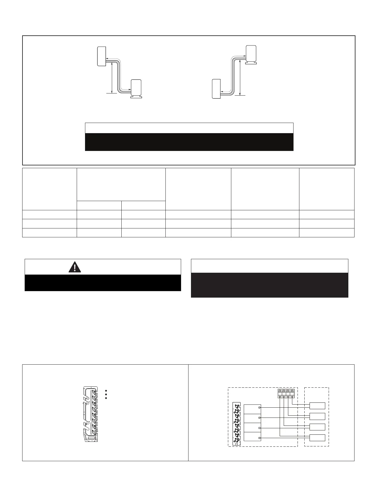
Connecting Multiple Capacity Indoor Units
• The largest capacity indoor unit must be connected to the lowest refrigerant connection ports on the outdoor unit.
• The 24,000 Btu indoor unit is only allowed to be connected to MPC036S4M, MPC048S4M, MLB036S4M and
MLB048S4M outdoor units.
NOTE: Each indoor unit must be piped AND wired to the correct zone piping connections and wiring terminals. Make
sure that indoor unit A is wired to the zone A terminal block and connected to the appropriate refrigerant pipe
connections.
A(1/2in)
A(1/4in)
B(3/8in)
B(1/4in)
C(3/8in)
C(1/4in)
Connecting Multiple Capacity
Indoor Units
Four-Zone System Example
A
B
C
D
Unit D
Unit D
Unit C
Unit B
Unit A
Unit C
Unit B
Unit A
wire
pipe
outdoor
indoor
L4(ft)
L3(ft)
L2(ft)
L1(ft)
Pipe and Wire Each Zone
Separately
 Loading...