Page 29
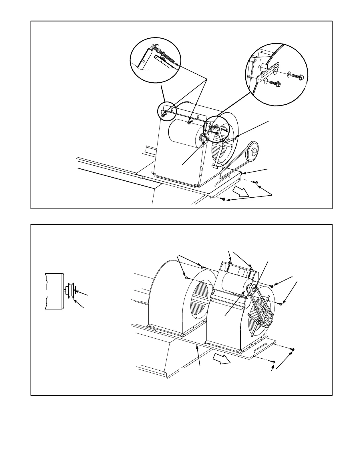
FIGURE 12
BLOWER ASSEMBLY SCA120
TO INCREASE CFM
LOOSEN ALLEN SCREW &
TURN PULLEY CLOCKWISE
TO DECREASE CFM
TURN PULLEY
COUNTERCLOCKWISE
BLOWER
MOTOR
PULLEY
BLOWER ASSEMBLY
SLIDING BASE
BELT TENSION
ADJUSTING
BOLTS
BLOWER WHEEL BRACKET IS
H−STYLE ON 20− & 25−TON UNITS
REMOVE SCREWS TO
SLIDE BLOWER
ASSEMBLY OUT OF UNIT
SIDE VIEW
CAV UNITS:
FIGURE 13
BLOWER ASSEMBLY (SCA240 & SCB288)
TO INCREASE BELT TENSION
1−Loosen four screws securing blower motor to
sliding base.
2−Turn adjusting screw to the left, or counter-
clockwise, to move the motor downward and
tighten the belt.
3−Tighten four screws.
TO INCREASE CFM
LOOSEN ALLEN SCREW &
TURN PULLEY CLOCKWISE
TO DECREASE CFM
TURN PULLEY
COUNTERCLOCKWISE
LOOSEN SCREWS
TO ADJUST BELT
TENSION
BLOWER
MOTOR
REMOVE SCREWS TO SLIDE
BLOWER ASSEMBLY OUT OF UNIT
LOOSEN SCREWS TO
ADJUST BELT TENSION
PULLEY
ALLEN
SCREW
BELT TENSION
ADJUSTING SCREWS
BLOWER
ASSEMBLY
SLIDING BASE
PULLEY
MOTOR
ALLEN
SCREW
SIDE VIEW
CAV UNITS:

 Loading...


