Page 41
F−Smoke Detectors A17 and A64
Photoelectric smoke detectors are a factory installed op-
tion. The smoke detectors can be installed in the supply air
section (A64), return air section (A17), or in both the supply
and return air section. Wiring for the smoke detectors are
shown on the temperature control section (C2) wiring dia-
gram in back of this manual.
G−Blower Proving Switch S52
The blower proving switch monitors blower operation and
locks out the unit in case of blower failure. The switch is
N.O. and closes at .14" W.C. (34.9 Pa) The switch is
mounted on the upper left hand corner of the blower deck.
Wiring for the blower proving switch is shown on the tempera-
ture control section (C2) wiring diagram in back of this manual.
H−Drain Pan Overflow Switch S149 (optional)
The overflow switch is used to interrupt cooling operation
when excessive condensate collects in the drain pan. The
N.O. overflow switch is controlled by K220 and DL46 relays,
located in the unit control panel. When the overflow switch
closes, 24VAC power is interrupted and after a five−second
delay unit compressors are de−energized. Once the con-
densate level drops below the set level, the switch will open.
After a five−minute delay the compressor will be energized.
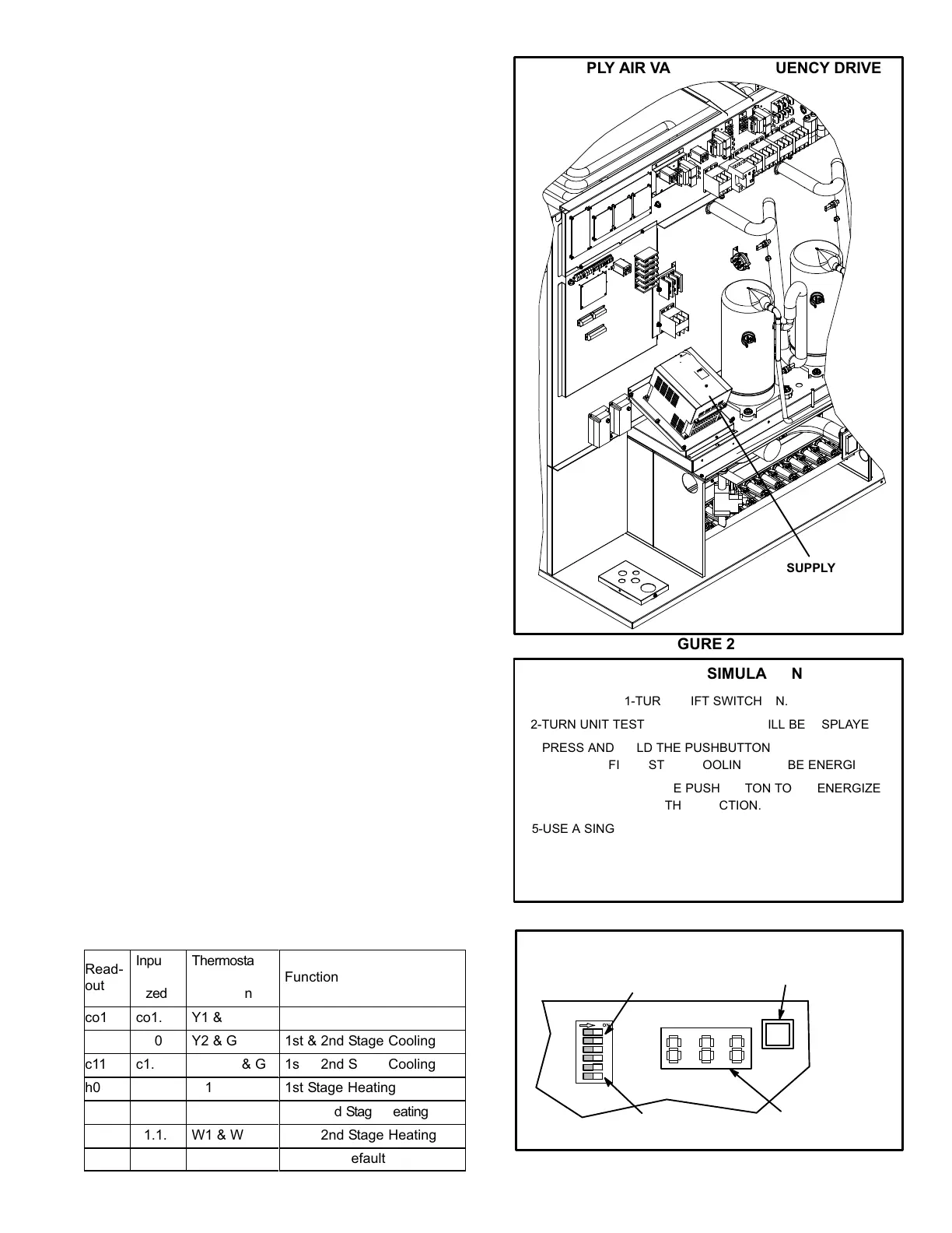
I−Multi−Staged Air Volume (MSAV) Blowers
Units may contain a supply air blower equipped with a variable
frequency drive A96 (VFD) which stages supply air CFM.
The supply air VFD (A96) is located near the compressors.
See figure 26.
MSAVt Unit Start−Up
Use the IMC to simulate a thermostat input to check unit
mechanical operation.
Use figures 27 and 28 and table 13, to initiate blower, cool-
ing, and heating functions. Refer to the IMC manual pro-
vided with each unit. Follow the blower, cooling, and heat-
ing operation and adjustments sections in this manual.
Make sure to check blower and compressor rotation, refrig-
erant pressures, gas pressures and heating operation.
TABLE 13
TESTING INPUTS (TWO−STAGE)
Read-
out
Input
Ener-
gized
Thermostat
Input
Simulation
ÁÁÁÁÁÁÁÁÁ
ÁÁÁÁÁÁÁÁÁ
ÁÁÁÁÁÁÁÁÁ
ÁÁÁÁÁÁÁÁÁ
Function
co1
co1.
Y1 & G
1st Stage Cooling
c10
c1.0
Y2 & G
1st & 2nd Stage Cooling
c11
c1.1
Y1, Y2, & G
1st & 2nd Stage Cooling
h01
h01.
W1
1st Stage Heating
h10
h1.0
W2
1st & 2nd Stage Heating
h11
h1.1.
W1 & W2
1st & 2nd Stage Heating
S01
S01.
SMOKE
Unit Off (Default)
FIGURE 26
SUPPLY AIR VARIABLE FREQUENCY DRIVE
SUPPLY AIR
VFD (A96)
THERMOSTAT SIMULATION
1−TURN SHIFT SWITCH ON.
2−TURN UNIT TEST SWITCH ON. CO1 WILL BE DISPLAYED.
3−PRESS AND HOLD THE PUSHBUTTON UNTIL A DECIMAL
APPEARS. FIRST STAGE COOLING WILL BE ENERGIZED.
4−PRESS AND HOLD THE PUSHBUTTON TO DE−ENERGIZE
THE FUNCTION.
5−USE A SINGLE PUSH TO ADVANCE TO THE NEXT FUNC-
TION OR A DOUBLE PUSH TO REVERSE TO THE PRE-
VIOUS FUNCTION. PUSH BUTTON AND HOLD TO ENER-
GIZE AND DE−ENERGIZE DISPLAYED FUNCTION.
FIGURE 27
SHIFT
SWITCH
A55 (M1−8) MAIN CONTROL BOARD
LED
READOUT
PUSHBUTTON
MODE
UNIT TEST
RECALL
ECTO
TEMP
OPT2
SHIFT
TEST
SWITCH
IMC BOARD
FIGURE 28

 Loading...


