Page 46
507964-01 9/2019
Measure the intake air CFM. If the CFM is lower than the
design specified CFM for ventilation air, use the Unit
Controller to increase the damper percent open. If the CFM is
higher than specified, decrease the damper percent open.
Note - Intake air CFM can also be determined using the
outdoor air temperature, return air temperature and mixed
air temperature. Refer to the economizer or outdoor air
damper installation instructions.
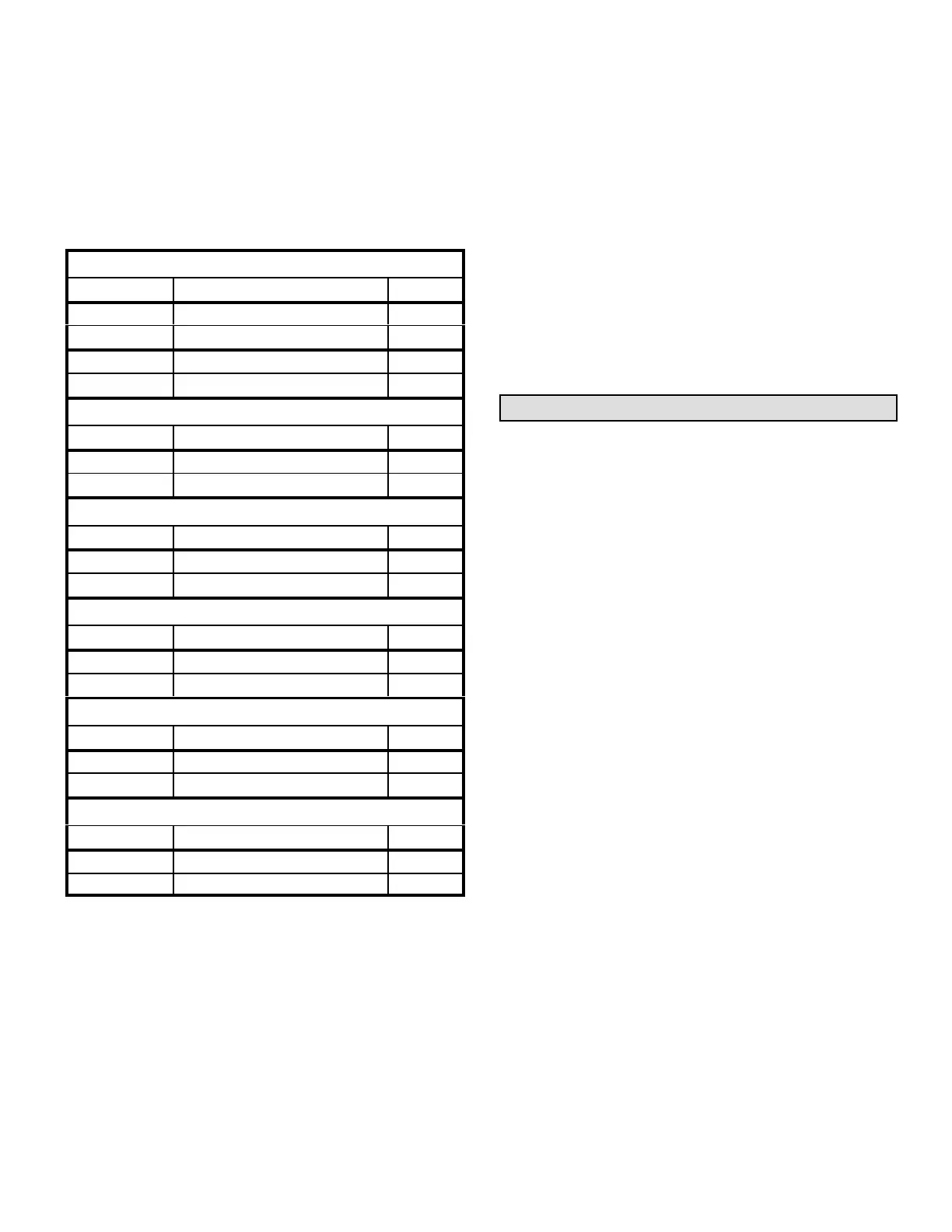
TABLE 25
MINIMUM AND MAXIMUM CFM
Gas Heat Minimum CFM
Unit Gas Heat Size Airflow CFM
SG 120 Std. , Med. 2225
SG 120 High 2550
SG 240 Std. , Med. 4450
SG 240 High 5075
Electric Heat Minimum CFM
Unit Heat Size (kW) Airflow CFM
SC 120 0, 15, 20, 30, 40, 45, 60 3800
SC 240 0, 20, 30, 40, 60, 80, 90 8000
Cooling Minimum CFM - 220 CFM/ton
Unit Blower Speed Airflow CFM
SG/SC 120 Low, Med. Low, Med. High 2200
SG/SC 240 Low, Med. Low, Med. High 4400
Cooling Minimum CFM - 280 CFM/ton
Unit Blower Speed Airflow CFM
SG/SC 120 High 2800
SG/SC 240 High 5600
Smoke and Ventilation Minimum CFM - 150 CFM/ton
Unit Not Applicable Airflow CFM
SG/SC 120 NA 1500
SG/SC 240 NA 3000
Heating and Cooling Maximum CFM - 480 CFM/ton
Unit Blower Speed Airflow CFM
SG/SC 120 High 4800
SG/SC 240 High 9600
Set Minimum Position 2
Use the same menu in the Unit Controller to set “Min OCP
Blwr High” for the blower CFM above the “midpoint” CFM.
When navigating into this menu, the Unit Controller will
bring on the corresponding blower speed and allow damper
position adjustment.
Settings / Control / MSAV / Damper / High Speed
Measure the intake air CFM. If the CFM is lower than the
design specified CFM for ventilation air, use the Unit
Controller to increase the damper percent open. If the CFM is
higher than specified, decrease the damper percent open.
Note - Intake air CFM can also be determined using the
outdoor air temperature, return air temperature and mixed
air temperature. Refer to the economizer or outdoor air
damper installation instructions.
MSAV
TM
Operation
This is a summary of cooling operation. Refer to the
sequence of operation provided in the Engineering
Handbook or Service Manual for more detail.
A-Two-Stage T'Stat; 2- and 4-Compressor Units
1-Economizer With Outdoor Air Suitable
Y1 Demand -
Compressors Off
Blower Cooling Low
Dampers modulate
Y2 Demand -
Compressors Off
Blower Cooling High
Dampers Modulate
Note - If dampers are at maximum open for three minutes,
compressor 1 and 2 are energized and blower stays on
cooling high.
2-No Economizer or Outdoor Air Not Suitable
Y1 Demand -
First-stage Compressors On
(compressor 1 on 120 units,
compressor 1 & 2 on 240 units)
Blower Cooling Low
Dampers Minimum Position
Y2 Demand -
All Compressors On
Blower Cooling High
Dampers Minimum Position
B-Zone Sensor (4 Clg. Stages), 4-Compressor Units
(240 Units)
1-Economizer With Outdoor Air Suitable
Y1 Demand -
 Loading...