Page 7
2 - Level the unit from side-to-side and from front-to-rear.
If the furnace is not level, place fireproof wedges or
shims between the low side of the furnace and the
floor. Make sure the weight of the furnace is distributed
evenly on all four corners. Strain on sides of cabinet
may occur if furnace weight is not evenly distributed.
This strain can cause cracking and popping noises.
Adjustments
Neither the nozzle setting nor the air adjustments are facto
ry set. The furnace is fire-tested and the limit control is
checked to make sure it functions properly; no factory set
tings are made. During installation, the furnace must be ad
justed to ensure proper operation. The installing dealer/
contractor must have and use proper test equipment in
order to correctly adjust the oil furnace. Proper testing
equipment is required to ensure correct operation of the
unit. The use of test equipment is more critical than ever
due to tighter tolerances needed to keep the furnace oper
ating efficiently.
Among the required test equipment for an oil furnace, the
proper combustion test kit should contain the following:
D Draft gauge
D CO
2
or O
2
Analyzer
D Smoke tester
D Pressure gauge
D High temperature thermometer
D Oil vacuum gauge
D Beckett T-501 nozzle gauge
D Knowledge of proper test equipment operation
CAUTION
Improper nozzle and/or air adjustment of this unit
may result in sooting problems. Refer to the follow
ing section for correct adjustment procedures.
Nozzle Adjustment
Proper adjustment of the nozzle assembly is critical. Before
the flue pipe and oil lines are installed, the nozzle assembly
must be checked for proper depth and alignment. You must
remove the entire burner assembly (not just the nozzle) from
the furnace to check the nozzle depth and alignment. The
smaller sized firing nozzle has been factory-installed. This
should be verified by the installer. A larger nozzle has been
provided in the bag assembly for use with SLO185BV105
and 141 units. Inspect the spark transformer leads also to en
sure they are still attached to the electrodes.
The burner assembly is attached to the vestibule panel by
three nuts. Slots are provided in the mounting flange for re
moving the burner assembly from the vestibule. Loosen the
nuts and turn the whole burner assembly clockwise (figure
6) to remove the entire burner assembly from the furnace.
There is adequate wire to remove the burner without discon
necting wires. Once removed, turn the burner around in the
vest panel area.
Figure 6
SLO185BV Series Burner Removal
First, loosen three nuts which
attach burner to vest panel.
Next, rotate burner clockwise
on slots then pull toward you.
To check the ignition electrode gap use the T-501 gauge.
The proper gap should be 5/32”.
To check nozzle alignment, again insert the small end of
gauge into the end cone and measure the nozzle and
electrode alignment against the center lines marked on
the gauge (again refer to enclosed illustration sheet). If
the nozzle is not centered, but found to be too far left or
right, a new nozzle assembly will need to be ordered. Do
not attempt to adjust by bending the 90 degree elbow in
the oil line.
Take care to properly re-install burner assembly when
nozzle adjustment has been completed.
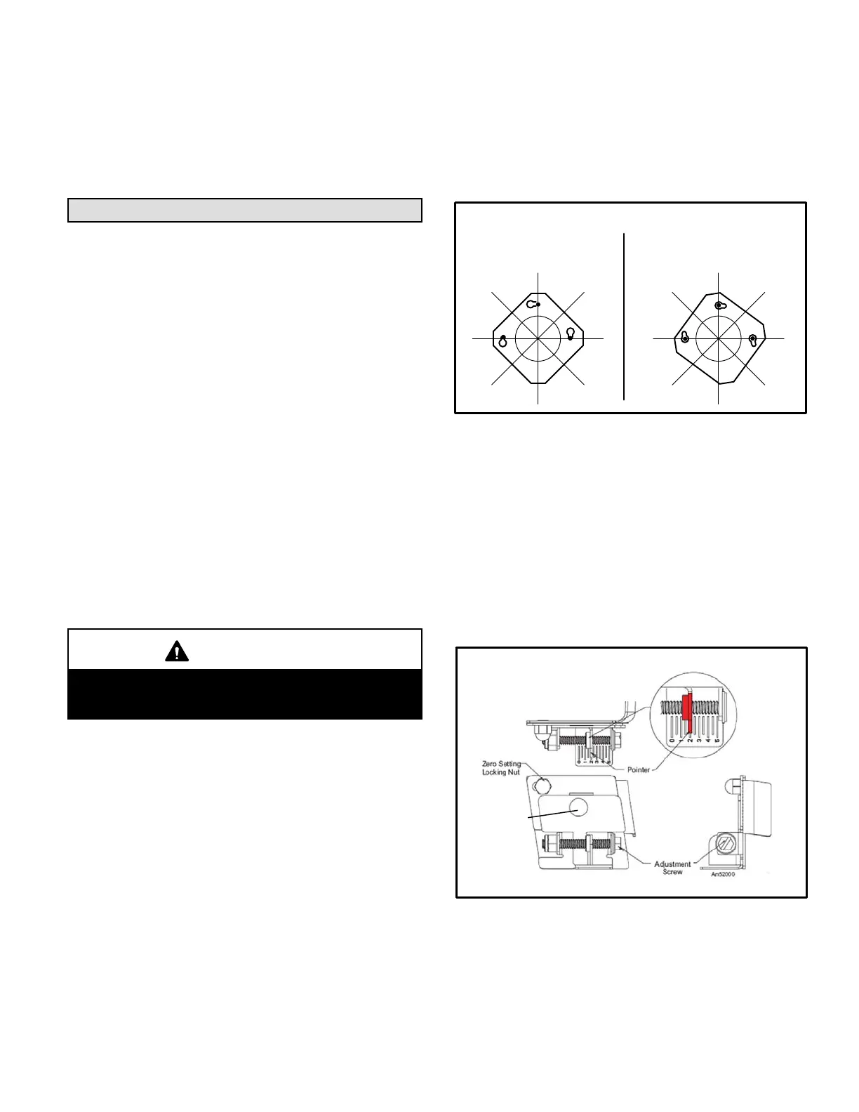
Figure 7
Beckett Oil Burner Nozzle Adjustment
Burner must be removed from
furnace for this procedure.
Splined Nut
 Loading...


