Page 20
Blower Control (A54)
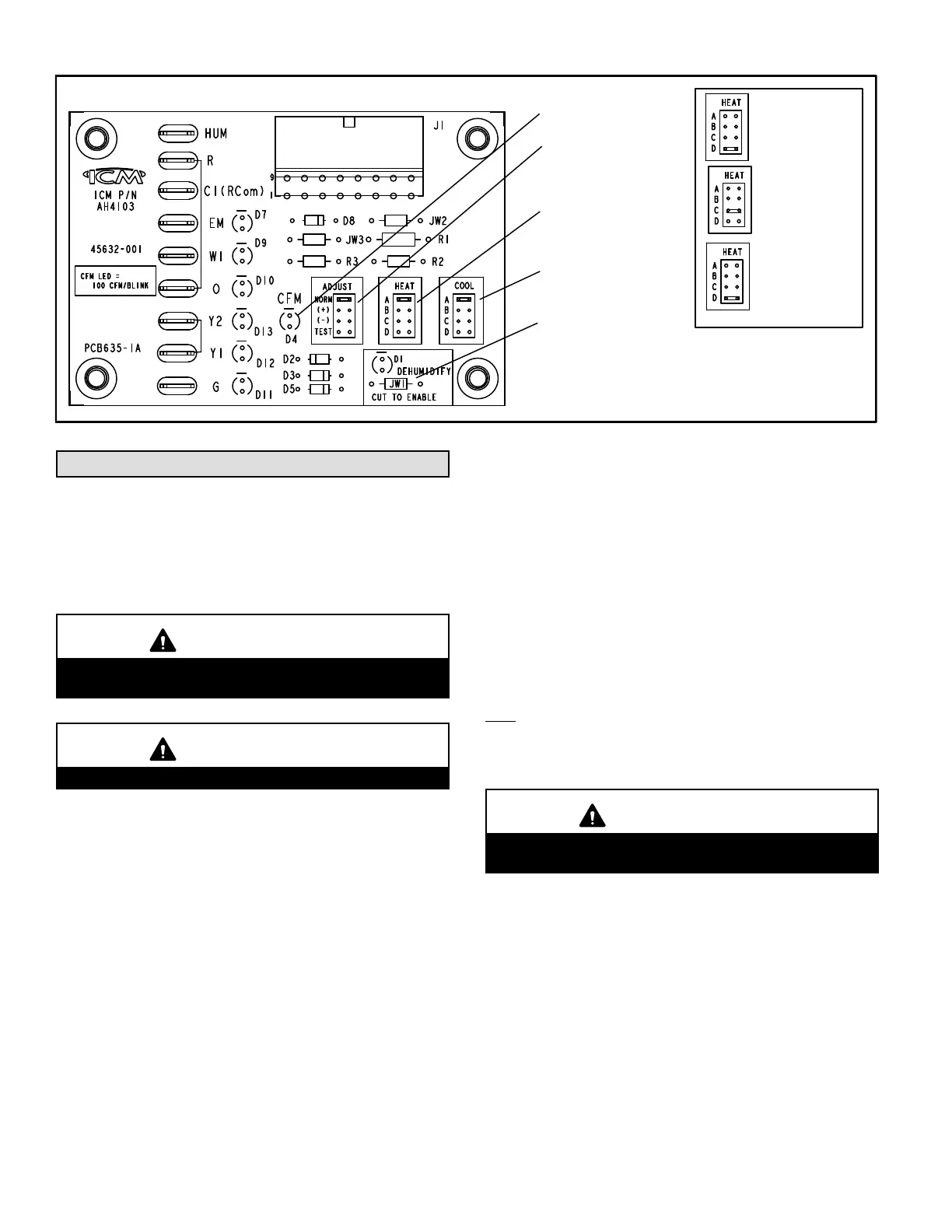
Figure 19
16-PIN PLUG
(BOARD TO MOTOR)
CFM LED
ADJUST
SELECTOR PINS
(Setting affects
cooling only)
HEATING SPEED
SELECTOR PINS (SEE
TABLE)
COOLING SPEED
SELECTOR PINS
NOTE - The JW1 resistor
must be cut to activate the
HUM terminal.
SLO185B-79
SLO185B-105
HEAT SPEED PINS
(JUMPERS)
NOTE - Do NOT move
heat speed jumpers
from factory settings.
SLO185BR-124
SLO185BF-124
SLO185BF-141
SLO185BR-141
Start-Up & Adjustment
Before starting unit, make sure the oil tank is adequately
filled with clean No. 1 or No. 2 furnace oil.
NOTE - Water, rust or other contaminants in oil supply sys
tem will cause malfunction and failure of the internal parts
of the fuel unit.
CAUTION
Never burn garbage or paper in the heating system.
Never leave papers near or around the unit.
CAUTION
Blower access door must be in place before start‐up.
Burner Start-Up
1 - Set thermostat for heating demand and turn on electri
cal supply to unit.
2 - Open all shut-off valves in the oil supply line to the
burner.
3 - While the ignition is on, press and release the reset
button on the burner control (hold 1/2 second or less).
If the control has not locked out since its most recent
complete heat cycle, the lockout time will be extended
to 4 minutes and the ignition will remain on for the en
tire heat cycle.
4 - Bleed the pump until all froth and bubbles are purged.
The bleed port is located on the bottom of the fuel
pump. To bleed, attach a clear plastic hose over the
vent plug. Loosen the plug and catch the oil in an
empty container. Tighten the plug when all the air has
been purged.
NOTE - A two-line fuel system will normally bleed itself
by forcing air back to the tank through the return line.
This type of bleeding procedure is not necessary.
5 - If burner fails to start within the set time, the burner
control will lock out operation. Press the reset button to
reset the control as in step 3. See figure 2 on page 3 for
burner parts arrangement.
NOTE - The reset button can be held for 15 seconds
for the Beckett 7505B primary control, at any time to
reset the controls lockout counter to zero and send the
control to standby.
CAUTION
Do not push the reset button on the primary control
more than one time.
6 - Repeat steps 4 and 5, if necessary, until pump is fully
primed and oil is free of bubbles. Then, terminate the
call for heat. The burner control will resume normal op
eration
Fuel Pump Pressure Adjustment
Measure fuel pump pressure with unit off. Attach pressure
gauge to pump outlet. Turn unit on and check pressure and
compare to table 9. Adjust if necessary.

 Loading...


