Page 21
Temperature Rise Adjustment
To measure temperature rise, place plenum thermometers
in warm air and return air plenums. Locate thermometer in
warm air plenum where thermometer will not “see” the heat
exchanger to prevent it from picking up radiant heat. Set
thermostat to its highest setting to start unit. After plenum
thermometers have reached their highest and steadiest
readings, subtract the readings. The difference in tempera
tures in the supply and return air plenums should approxi
mate the temperatures listed in table 8 and on the ap
pliance rating plate.
If the temperature rise is not within the range listed, check
the following items:
D Make sure that properly sized nozzle has been
used (table 9).
D Make sure that fuel pump pressure is correct.
D If furnace is in cutback mode, check for:
Dirty filters,
Dirty indoor coil,
Restricted ducts, closed registers, etc.
Table 8
Temperature Rise
Unit Temperature Rise °F
SLO185BV799 45 - 55
SLO185BV105 45 - 55
SLO185BV124 55 - 65
SLO185BV141 55 - 65
Limit Control
Limit Control — Do not adjust from factory setting.
Burner Adjustment
The following instructions are essential to the proper op
eration of SLO185BV series oil furnaces. Refer to table 9
for nozzle and pump pressure information. The proper way
to adjust an oil burner is with a CO
2
analyzer and smoke
gun. A properly adjusted burner will result in a quiet, clean
fire which will prevent sooting and minimize cleaning. Us
ing the following procedure will provide a margin of reserve
air to accommodate variable conditions.
1. Punch a 5/16” diameter service hole in the flue outlet.
This sampling hole should be at least two flue diamet
ers above the breech, or elbow at the breech, but
ahead of the barometric damper.
2. Operate burner for approximately 5 to 10 minutes.
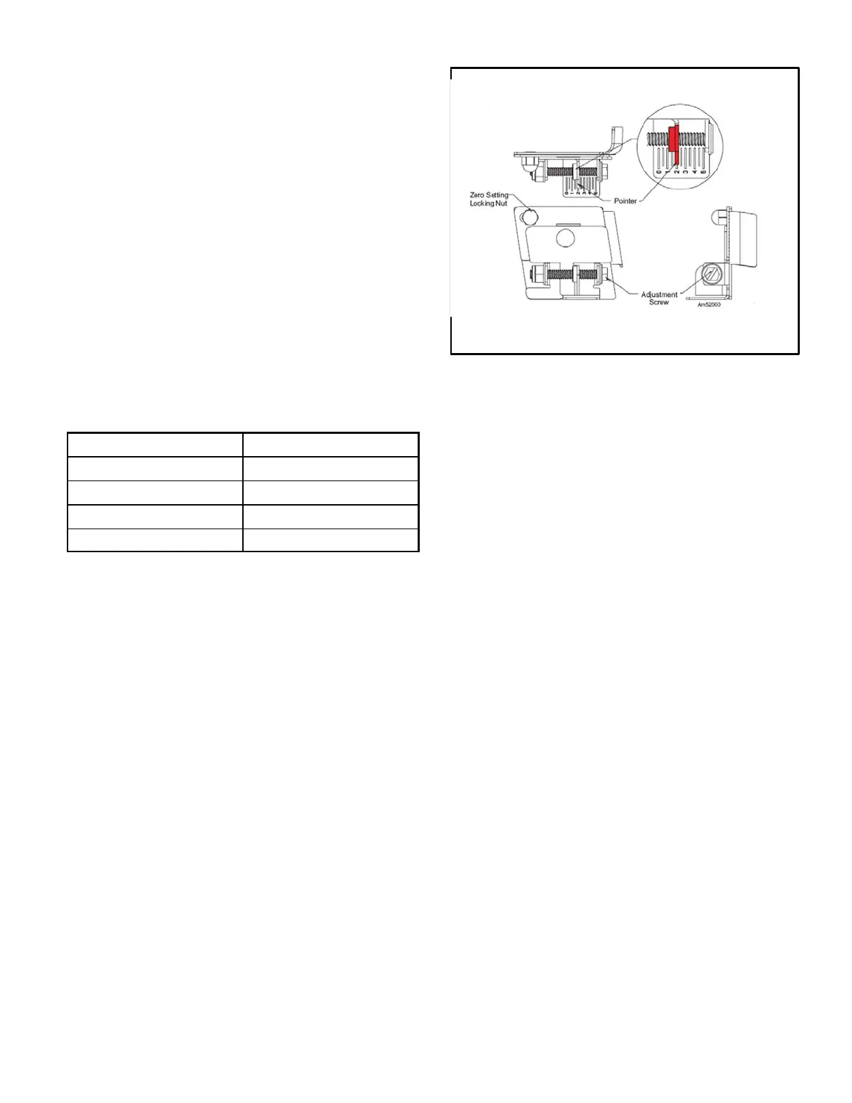
Beckett Oil Burner Nozzle Adjustment
Figure 20
3. Take a draft reading at the service hole in the flue out
let. Adjust barometric draft control in the stack to
achieve an overfire draft of -0,1” to -.02” and a breach
of -0.2 to -.04”.
4. Pull and record a smoke reading at the service hole us
ing an industry standard smoke tester.
5. If the burner is producing more than #1 smoke, adjust
the intake air using the zero setting locking nut and ad
justment screw (figure 20). Loosen the locking nut ap
proximately one turn. Turn the adjustment screw clock
wise to increase air or counterclockwise to decrease
air.
6. Once the desired smoke level is achieved, use a suit
able test instrument and take a CO
2
sample at the ser
vice hole in the flue outlet (from step1).
7. Adjust the air from step 5 to achieve the desired CO2
level.
8. Recheck smoke level.
9. Recheck draft and CO
2
reading at the service hole.
10. Using a suitable thermometer, obtain and record the
flue gas temperature at the service hole.
11. Use the CO
2
reading and the flue gas temperature
reading to determine unit efficiency.
12. When proper combustion and smoke readings have
been achieved, tighten the zero setting lock nut and
adjustment screw.
 Loading...


