Page 22
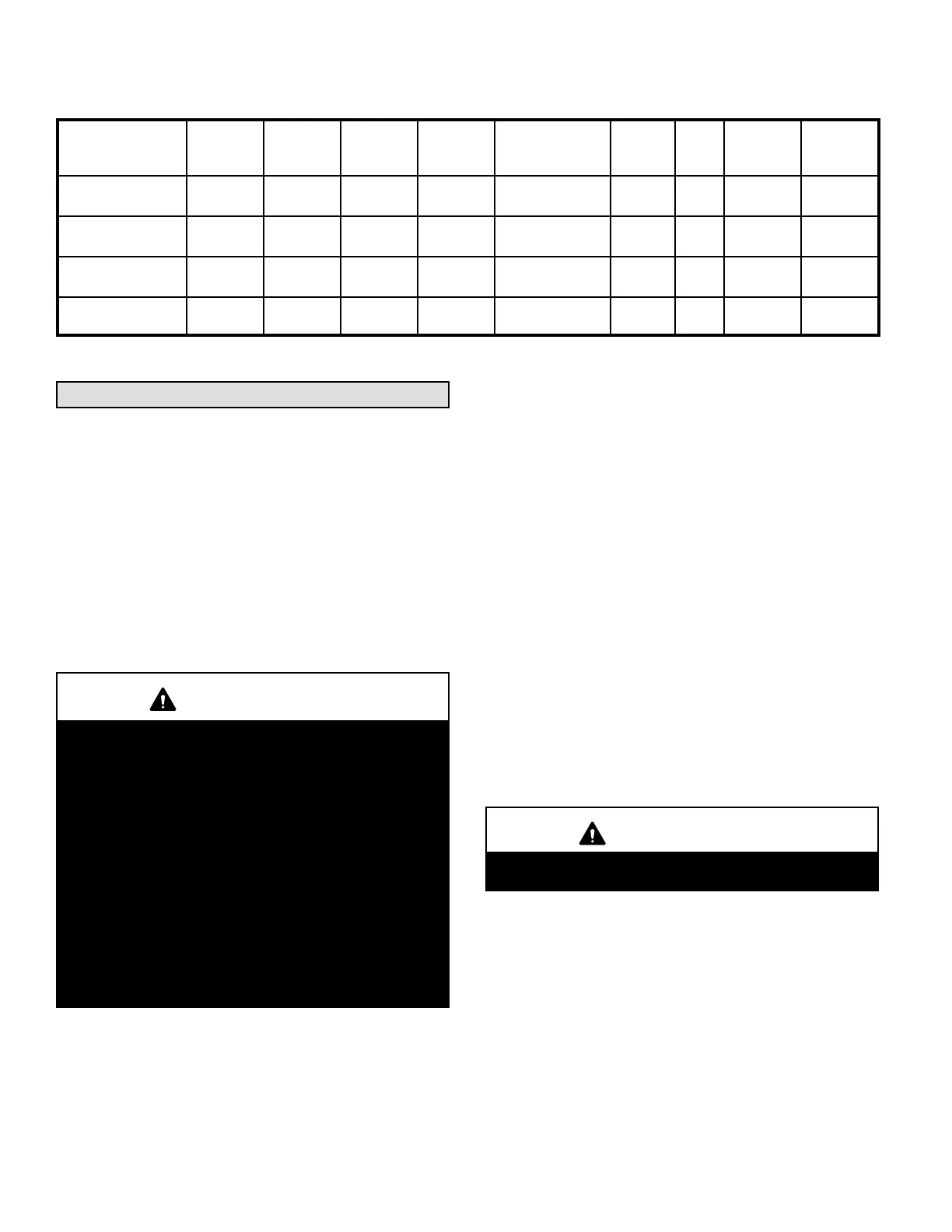
Table 9
Burner Specifications
Unit
Burner
Number
Beckett
Spec. No.
Beckett
Air Tube
Part No.
Input
Rating
BTU/HR
Nozzle Size,
Spray, Angle, &
Pattern
Pump
Pres
sure
Head
Insertion
Length
Static
Plate
Diameter
SLO185BV-79/105 103880-01 ARM2201 NX70LHHS 79,000
0.50gph x 60°A
hollow
150 6 Slot 5” 3.00”
SLO185BV-79/105 103880-01 ARM2201 NX70LHHS 105,000
*0.65gph x 60 °A
hollow
150 6 Slot 5” 3.00”
SLO185BV-124/141 103880-02 ARM2202 NX70LCHS 124,000
0.75gph x 60°A
hollow
145 6 Slot 5” 3.25”
SLO185BV-124/141 103880-02 ARM2202 NX70LCHS 141,000
*0.85gph x 60°A
hollow
145 6Slot 5” 3.25”
*Nozzle must be field-installed for conversion to higher heating input.
NOTE - All nozzles are Delavan brand.
Service
A - Servicing Filter
NOTE - Under no circumstances should the access panels
to the blower compartment be left off or left partially open.
1 - Throw‐Away Type Filters — Filters should be checked
monthly and replaced when necessary to assure prop
er furnace operation. Replace filters with like kind and
size filters.
2 - Reusable Type Filters — Filters should be checked
monthly and cleaned when necessary to assure prop
er furnace operation. Use warm water and a mild de
tergent. Replace filter when dry. Permanent filters
supplied with SLO185B furnaces do not require oiling
after cleaning. Examine filter label for any for special
instructions that may apply.
IMPORTANT
If a highefficiency filter is being installed as part of
this system to ensure better indoor air quality, the fil
ter must be properly sized. Highefficiency filters
have a higher static pressure drop than standardef
ficiency glass/foam filters. If the pressure drop is too
great, system capacity and performance may be re
duced. The pressure drop may also cause the limit to
trip more frequently during the winter and the indoor
coil to freeze in the summer, resulting in an increase
in the number of service calls.
Before using any filter with this system, check the
specifications provided by the filter manufacturer
against the data given in the appropriate Lennox
Product Specifications bulletin. Additional informa
tion is provided in Service and Application Note
ACC002 (August 2000).
B - Blower
Blower motor is pre‐lubricated and sealed for extended op
eration. No further lubrication is required. Disconnect pow
er to unit before cleaning blower wheel for debris.
C - Flue Pipe Inspection
The flue pipe should be inspected annually by a qualified
service technician. Remove and clean any soot or ash
found in the flue pipe. Inspect pipe for holes or rusted
areas. If replacement is necessary, replace with the same
size and type as required by code. Inspect the flue baro
metric draft control and replace if found to have failed.
D - Cleaning Heat Exchanger
1 - Remove the vent pipe from the furnace.
2 - Remove the locking screws and the caps from the
clean out tubes. Remove flue access elbow.
3 - Using a long spiral wire brush, sweep down the outer
drum of the heat exchanger. Then using the hose at
tachment, vacuum out loose debris.
4 - Remove the locking screw and cap from the observa
tion tube and with the spiral wire brush, reach upward
toward the rear of the heat exchanger to clean out the
crossover tube.
CAUTION
Do not attempt to clean the combustion chamber. It
can be easily damaged.
5 - Replace the clean out caps and flue access elbow.
Make sure locking screws are secure.
6 - Brush out and vacuum the vent outlet area of the outer
drum and replace vent pipe.
7 - Clean around burner, blower deck and vestibule area.
NOTE - A heat exchanger clean‐out kit ABRSH380
(35K09) is available from Lennox. The kit includes a ra
diator brush, a tapered brush and a non-metallic 36”
spiral wire handle.
 Loading...


