Page 17
Blower Control (A54)
WARNING
Electric shock hazard. Can cause
injury or death. Before attempting to
perform any service or maintenance,
turn the electrical power to unit OFF at
disconnect switch(es). Unit may have
multiple power supplies.
SLO185BV units are equipped with a variable speed blow
er motor which is capable of maintaining a specified CFM
throughout the external static range. The blower motor is
controlled by jumper selections made on the A54 blower
control. Jumpers are available to select both heating and
cooling blower speeds, as well as adjustment rates for
cooling blower speeds and a test mode. Blower control set
tings and operation are described in this section.
The units are factory-set for nominal airflow for each mod
el. Figure 19 shows the blower control. Use table 7 to deter
mine the correct air volume for operation in heat and cool
mode.
Read this section thoroughly before adjusting the jumpers
to obtain the appropriate blower speed.
To change jumper positions, gently pull the jumper off the pins
and re-position it across the pins that will give the desired blow
er speed. The following section outlines the different jumper
selections available and conditions associated with each
one (see figure 19).
IMPORTANT
The unit is not designed for use with the Harmony
zone control system.
COOL (single‐stage systems)
The COOL jumper is used to determine the CFM during
cooling operation. This jumper selection is activated for
cooling when Y1 is energized. A factory-installed jumper
from Y1 to Y2 allows single-stage cooling.
The blower motor runs at 82% CFM for the first 7-1/2 min
utes of each cooling demand to allow for greater humidity
removal and to conserve energy. If, after 7-1/2 minutes, the
Y demand is not met, 100% CFM is supplied until the de
mand is satisfied.
OFFCALL
100%
82%
Y
60
sec
7.5 minutes
82%
y
Y - Cool Demand Present
y - Cool Demand Satisfied
When the demand for cool is met, the blower ramps down
to 82% CFM for 60 seconds, then turns off.
COOL (two‐stage systems)
This unit is factory-wired for single-stage cooling. For
two-stage cooling operation, you must cut the jumper
wire from Y1 to Y2 on the A54 blower control. Cut the
jumper close to the Y1 terminal to allow a pigtail connection
with the remaining wire from the Y2 terminal and a wire
connected to the Y2 terminal of the two-stage thermostat.
Refer to field wiring diagrams.
A thermostat call for first‐stage cooling closes the R to Y1
circuit on the A54 blower control. The blower motor runs at
57% CFM for the first 7-1/2 minutes of the 1st-stage cooling
demand. After 7-1/2 minutes, the blower motor runs at 70%
CFM until the first-stage demand is satisfied.
OFFCALL
100%
70%
57%
Y1
7-1/2
minutes
60
sec
y2/Y1
Y1 - 1st-stage COOL Demand Present
y1
- 1st-stage COOL Demand Satisfied
Y2 - 2nd-stage COOL Demand Present
y2
- 2nd-stage COOL Demand Satisfied
Y1/Y2
70%
57%
y1
y1
OFF
60
sec
If first-stage cooling does not satisfy the demand, the ther
mostat calls for 2nd‐stage cooling, closing the R to Y2 cir
cuit on the A54 blower control. The blower motor ramps up
to 100% CFM.
When the Y2 demand is met, the blower ramps down to Y1
at 70% CFM until Y1 is met, and ramps down to 57% CFM
for 1 minute, then turns off.
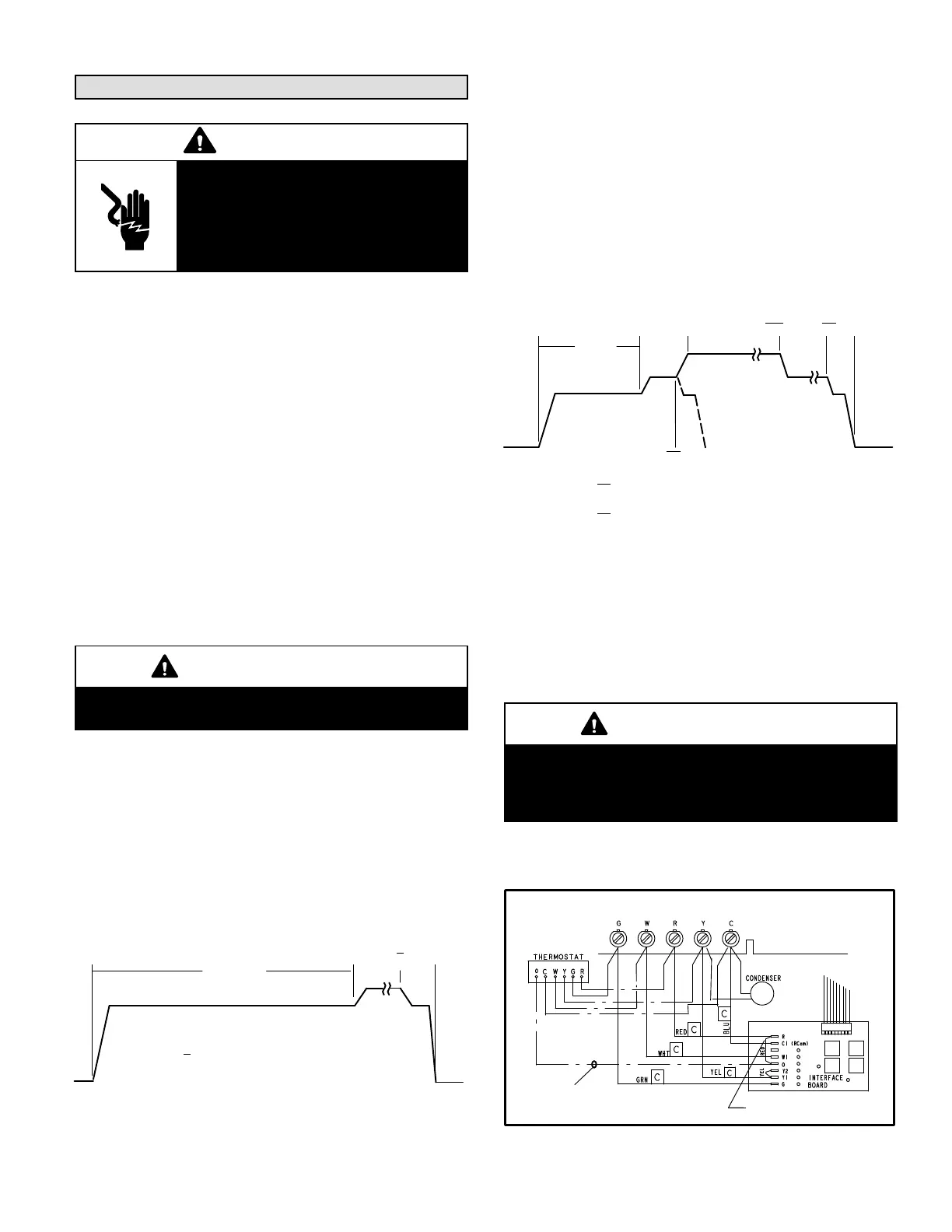
Heat Pump
IMPORTANT
For heat pump operation, cut the jumper between R
and O near the R terminal of A54 and connect the pig
tail to the thermostat O wire (A54 board “O” to ther
mostat “O”). See figure 18.
In heat pump mode, a call for heat pump operation follows
the same sequence as a call for cooling, with the exception
that there is a 30-second blower ramp-up to blower CFM.
Figure 18
A54
A15
Heat Pump Applications
Clip red jumper from R to O
close to R terminal.
Make pigtail
connection and run wire from
terminal O to O terminal on
thermostat.
To blower
motor
 Loading...


