Page 11
Discharge Air Temperature Sensor
This furnace is shipped with a discharge air temperature sensor that can be installed in the supply air plenum. The sen-
sor is used to measure temperature rise in the heating mode and temperature drop in the cooling mode. See TABLE 2
and FIGURE 15 (upow) or TABLE 3 and FIGURE 16 (horizontal left) or TABLE 4 and FIGURE 17 (horizontal right) for
correct location. Drill a 3/8 inch diameter hole in the supply duct based on the specied location. Center the discharge
air temperature sensor in the middle of the hole and use two eld provided screws to secure in place. The orientation of
the sensor mounting ange is not critical and can be oriented to whatever position is needed to prevent interference with
the evaporator coil, air duct etc. Field supplied wiring must be used to connect the discharge air temperature sensor to
the discharge air temperature sensor terminals on the integrated control board. Either wire can be connected to either
terminal. See FIGURE 18.
A communicating thermostat can be used to run temperature rise and temperature drop tests and viewed in the installa-
tion reports. See “FIGURE 53” on page 36 for communicating thermostat wiring. If a communicating thermostat is not
being used, then the discharge temperature can be viewed on the seven segment LED on the integrated control shown in
FIGURE 18. For zoning applications the discharge air sensor must be installed and wired to the zoning control board and
should not be wired to the furnace control board.
NOTE - The discharge air temperature sensor must be located per TABLE 2, TABLE 3 or TABLE 4 to provide an accurate
temperature measurement.
NOTE - If the system does not include an evaporation coil, the sensor should be installed according to the following:
1 - Place the sensor as far away from the direct heat source in the main plenum as possible. A minimum of 19” is recom
mended but up to 36” is preferred.
NOTE - If the system does not include an evaporation coil, the sensor should be installed according to the following:
1 - Place the sensor as far away from the direct heat source in the main plenum as possible. A minimum of 19” is recom
mended but up to 36” is preferred.
2 - Oset the sensor 1/4 of the width of the plenum from the left edge of the plenum in upow, top edge of the plenum in
horizontal right and bottom of the plenum in horizontal left. For example, if the plenum is 16” wide then oset the sensor 4”
from the edge. The sensor should report a temperature within the rise range of the furnace. If the readings from the sensor
appear to be below the rise range of the furnace, move the sensor in 1” increments towards the center of the plenum until
the sensed temperature is within the rise range of the furnace. If the sensor reading appears to be too high, move the sen-
sor in 1” increments towards the edge of the plenum until the sensed temperature is within the rise range of the furnace.
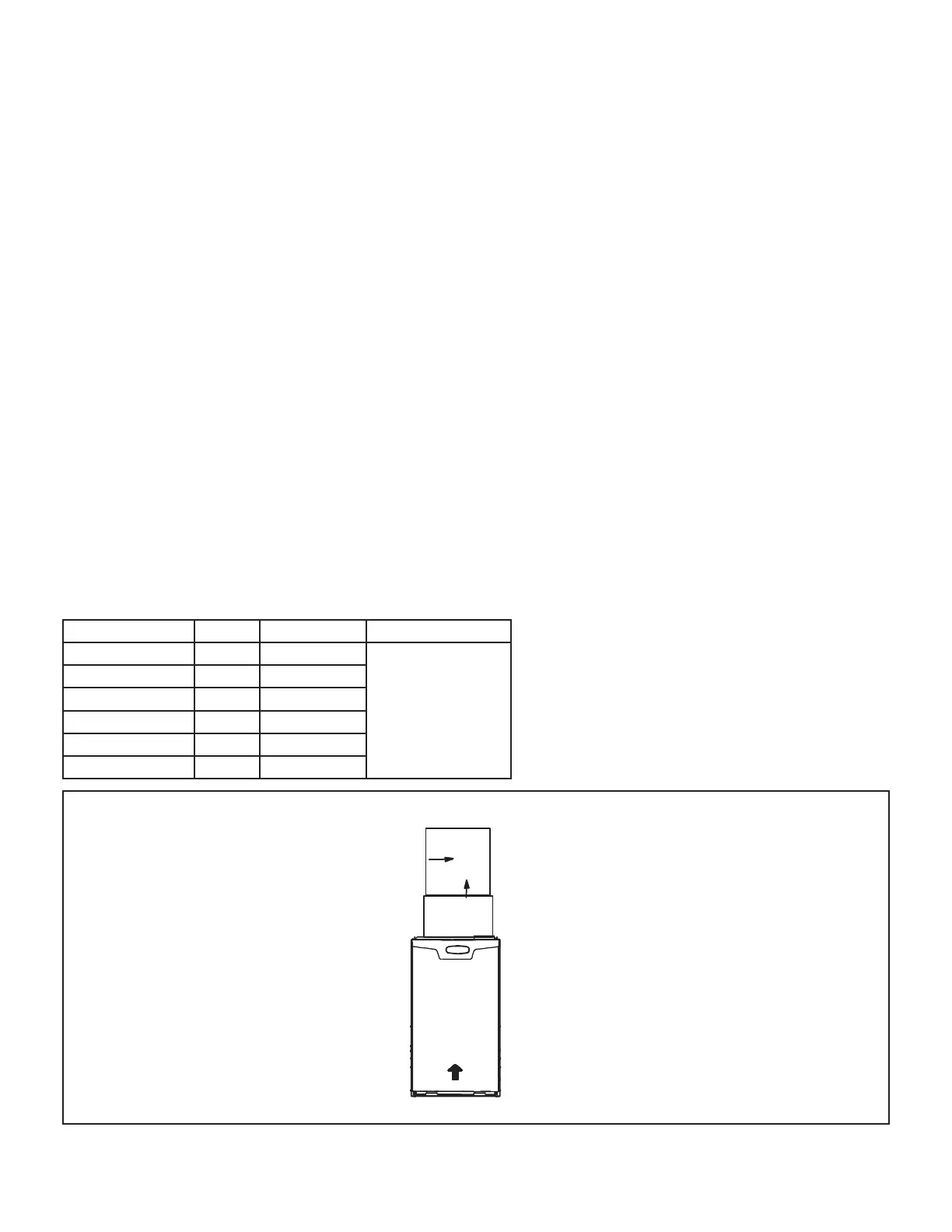
TABLE 2
Discharge Air Temperature Sensor Location Upow
SLP99UH Model “a” “b” Mounting Surface
070XV36B 2” Center
Plenum
Duct
090XV36C 3” Center
090XV48C 2” 7” from right
090XV60C 3” 4” from left
110XV60C 2” 8” from right
135XV60D 2” 7” from left
Coil
Plenum
a
b
Upflow
AIR FLOWAIR FLOW
Discharge Air Temperature Sensor Location
FIGURE 15
 Loading...


