Page 10
NOTE - When the furnace is installed on a platform in a
crawlspace, it must be elevated enough to avoid water
damage and to allow the evaporator coil to drain.
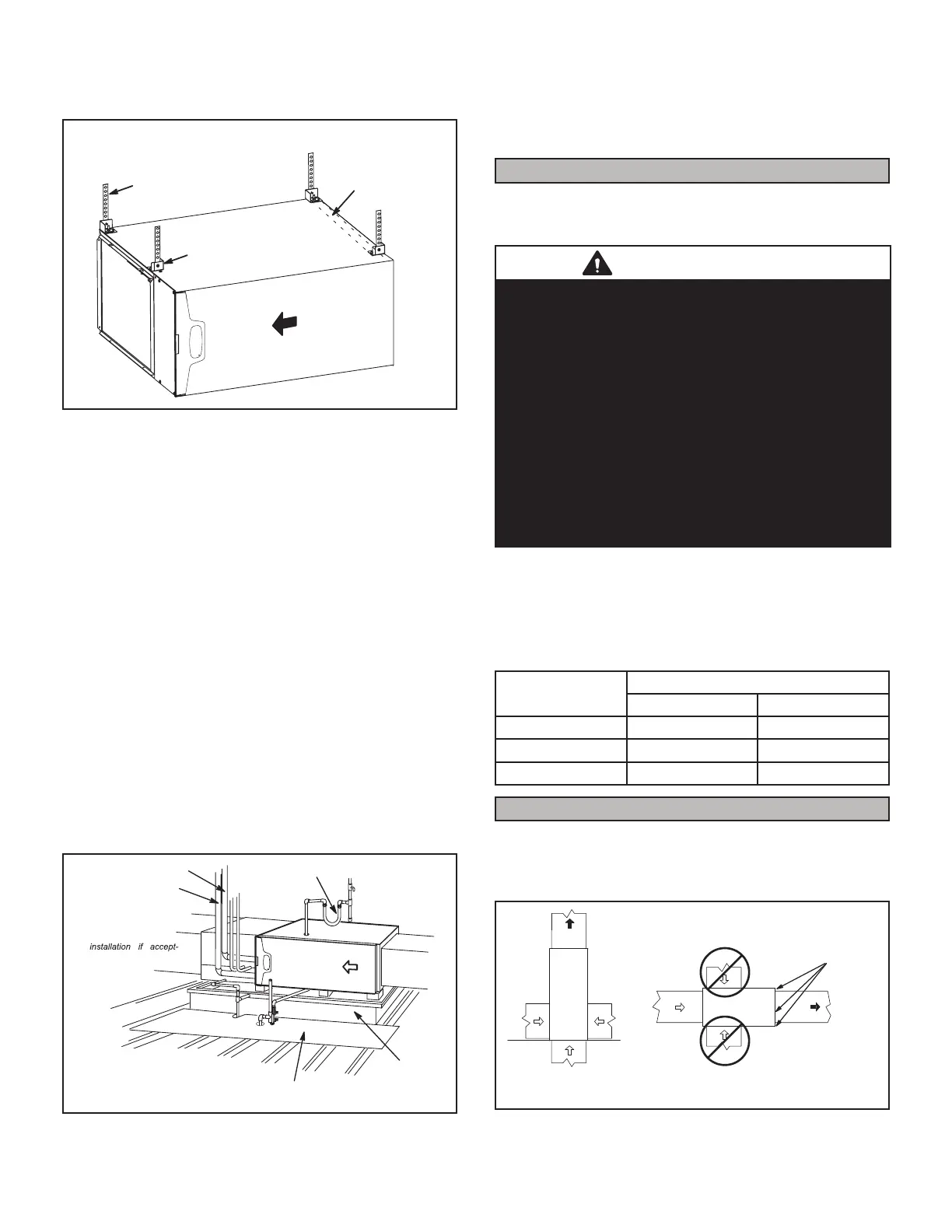
HORIZONTAL SUSPENSION KIT
Bracket
(typical)
Metal Strap
(typical)
Air
Flow
Internal Brace
(provided with kit)
FIGURE 12
Platform Installation of Horizontal Unit
1 - Select location for unit keeping in mind service and
other necessary clearances. See FIGURE 11.
2 - Construct a raised wooden frame and cover frame
with a plywood sheet. If unit is installed above
nished space, fabricate an auxiliary drain pan
to be installed under unit. Set unit in drain pan as
shown in FIGURE 13. Leave 8 inches for service
clearance below unit for condensate trap.
3 - Provide a service platform in front of unit. When
installing the unit in a crawl space, a proper support
platform may be created using cement blocks.
4 - Route auxiliary drain line so that water draining from
this outlet will be easily noticed by the homeowner.
5 - If necessary, run the condensate line into a
condensate pump to meet drain line slope
requirements. The pump must be rated for use
with condensing furnaces. Protect the condensate
discharge line from the pump to the outside to avoid
freezing.
6 - Continue with exhaust, condensate and intake
piping installation according to instructions.
*Gas connector may be
used for Canadian
able by local authority
having jurisdiction.
*GAS CONNECTION
RAISED
PLATFORM
SERVICE PLATFORM
INTAKE PIPE
EXHAUST PIPE
FIGURE 13
Return Air -- Horizontal Applications
Return air must be brought in through the end of a fur-
nace installed in the horizontal position. The furnace is
equipped with a removable bottom panel to facilitate in-
stallation. See FIGURE 7.
Filters
This unit is not equipped with a lter or rack. A eld-provid-
ed lter is required for the unit to operate properly. TABLE
1 lists recommended lter sizes.
IMPORTANT
If a higheciency lter is being installed as part of this
system to ensure better indoor air quality, the lter must
be properly sized. Higheciency lters have a higher
static pressure drop than standard eciency glass/foam
lters. If the pressure drop is too great, system capacity
and performance may be reduced. The pressure drop
may also cause the limit to trip more frequently during
the winter and the indoor coil to freeze in the summer,
resulting in an increase in the number of service calls.
Before using any lter with this system, check the
specications provided by the lter manufacturer against
the data given in the appropriate Lennox Product
Specications bulletin. Additional information is provided
in Service and Application Note ACC002 (August 2000).
A lter must be in place when the unit is operating.
NOTE - In upow applications where side return air lter is
installed on same side as the condensate trap, make sure
that clearance is maintained to ensure future access to
the lter access panel.
TABLE 1
Furnace
Cabinet Width
Filter Size
Side Return Bottom Return
17-1/2” 16 X 25 X 1 (1) 16 X 25 X 1 (1)
21” 16 X 25 X 1 (1) 20 X 25 X 1 (1)
24-1/2” 16 X 25 X 1 (2) 24 X 25 X 1 (1)
Duct System
Use industry-approved standards to size and install the
supply and return air duct system. This will result in a qui-
et and low-static system that has uniform air distribution.
See below for proper duct installation.
FIGURE 14
HORIZONTAL UNIT
SUPPLY
AIR
SUPPLY
AIR
Install self tapping screws
to seal any potential air
leaks
UPFLOW UNIT
 Loading...


