Page 9
Top
Bottom (Floor)
Left Side Right Side
Top/Plenum 1 in. (25 mm)
*Front 0
Back 0
Sides 0†
Vent 0
Floor 0‡
*Front clearance in alcove installation must be 24 in. (610 mm).
Maintain a minimum of 24 in. (610 mm) for front service access.
†Allow proper clearances to accommodate condensate trap.
‡For installations on a combustible floor, do not install the furnace
directly on carpeting, tile or other combustible materials other
than wood flooring.
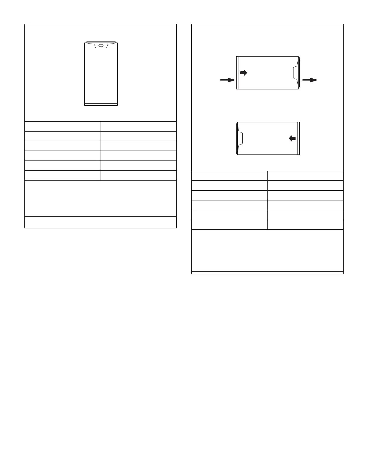
FIGURE 10
Return Air -- Upow Units
Return air can be brought in through the bottom or either
side of the furnace installed in an upow application. If the
furnace is installed on a platform with bottom return, make
an airtight seal between the bottom of the furnace and the
platform to ensure that the furnace operates properly and
safely. The furnace is equipped with a removable bottom
panel to facilitate installation.
Markings are provided on both sides of the furnace cabinet
for installations that require side return air. Cut the furnace
cabinet at the maximum dimensions shown on page 2.
Refer to Engineering Handbook for additional information.
Setting an Upow Unit
When the side return air inlets are used in an upow appli-
cation, it may be necessary to install shims on the bottom
of the furnace.
Horizontal Applications
The SLP99UHV furnace can be installed in horizontal ap-
plications with either right- or left-hand air discharge. Re-
fer to FIGURE 11 for clearances in horizontal applications
Installation Clearances
dnE thgiRdnE tfeL
Right-Hand Discharge
Left-Hand Discharge
Top
Bottom (Floor)**
Bottom (Floor)**
dnE thgiRdnE tfeL
Air
Flow
Air
Flow
AIR FLOW
AIR FLOW
Top 0
Front* 0
Back 0
Ends 0
Vent 0
Floor 0‡
*Front clearance in alcove installation must be 24 in. (610 mm).
Maintain a minimum of 24 in. (610 mm) for front service access.
**An 8” service clearance must be maintained below the unit to
provide for servicing of the condensate trap.
‡For installations on a combustible floor, do not install the furnace
directly on carpeting, tile or other combustible materials other
than wood flooring.
FIGURE 11
Suspended Installation of Horizontal Unit
This furnace may be installed in either an attic or a crawl-
space. Either suspend the furnace from roof rafters or
oor joists, as shown in FIGURE 12, or install the furnace
on a platform, as shown in FIGURE 13. A horizontal sus-
pension kit (51W10) may be ordered from Lennox or use
equivalent.
NOTE - Heavy-gauge sheet metal straps may be used to
suspend the unit from roof rafters or ceiling joists. When
straps are used to suspend the unit in this way, support
must be provided for both the ends. The straps must not
interfere with the plenum or exhaust piping installation.
Cooling coils and supply and return air plenums must
be supported separately.
 Loading...


