Page 15
7 - Immediately after applying last coat of cement to
pipe, and while both inside socket surface and end
of pipe are wet with cement, forcefully insert end of
pipe into socket until it bottoms out. Turn PVC pipe
1/4 turn during assembly (but not after pipe is fully
inserted) to distribute cement evenly. DO NOT turn
ABS or cellular core pipe.
NOTE - Assembly should be completed within 20 sec-
onds after last application of cement. Hammer blows
should not be used when inserting pipe.
8 - After assembly, wipe excess cement from pipe at
end of tting socket. A properly made joint will show
a bead around its entire perimeter. Any gaps may
indicate a defective assembly due to insucient
solvent.
9 - Handle joints carefully until completely set.
Venting Practices
* See Piping and Fittings Specifications table
Piping Suspension Guidelines
NOTE - Isolate piping at the point where it exits the outside wall or
roof in order to prevent transmission of vibration to the structure.
SCHEDULE 40
PVC - 5'
all other pipe* - 3'
Wall
edistuoedisni
24” maximum
3/4” minimum
Wall Thickness Guidelines
FIGURE 19
1 - In areas where piping penetrates joists or interior
walls, hole must be large enough`to allow clearance
on all sides of pipe through center of hole using a
hanger.
2 - When furnace is installed in a residence where unit
is shut down for an extended period of time, such
as a vacation home, make provisions for draining
condensate collection trap and lines.
Exhaust Piping FIGURE 23, FIGURE 24 and FIGURE
26 (vent adapter)
3 - Route piping to outside of structure. Continue with
installation following instructions given in piping
termination section..
Intake Piping FIGURE 23 and FIGURE 24
The SLP99UHV furnace may be installed only in direct
vent applications.
The SLP99UHV is designed for combustion air intake
through an inlet in the unit’s top cap. Intake air piping is
independent of exhaust piping.
If replacing a furnace which was
commonly vented with another gas appliance, the size
of the existing vent pipe for that gas appliance must be
checked. Without the heat of the original furnace flue
products, the existing vent pipe is probably oversized for
the single water heater or other appliance. The vent
should be checked for proper draw with the remaining
appliance.
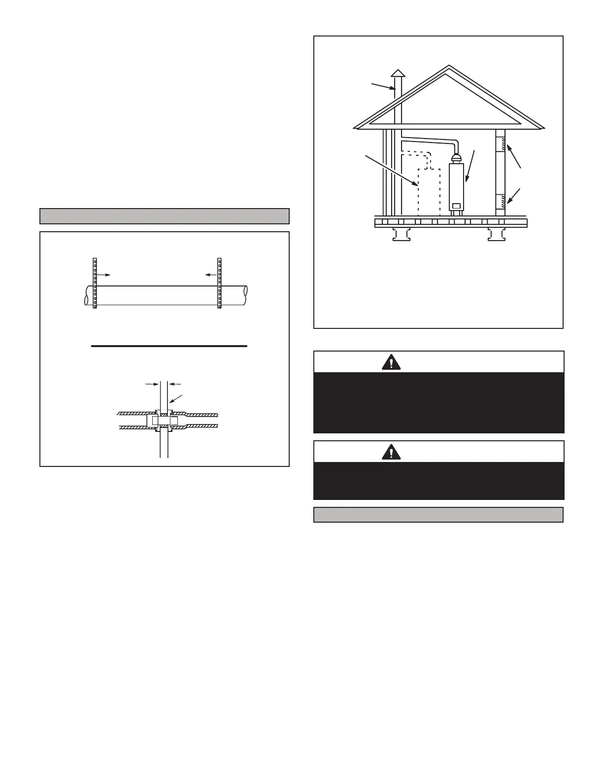
REPLACING FURNACE THAT WAS PART OF A
COMMON VENT SYSTEM
CHIMNEY
OR GAS
VENT
(Check sizing
for water
heater only)
FURNACE
(Replaced)
WATER
HEATER
OPENINGS
(To Adjacent
Room)
FIGURE 20
CAUTION
Do not discharge exhaust into an existing stack or
stack that also serves another gas appliance. If vertical
discharge through an existing unused stack is required,
insert PVC pipe inside the stack until the end is even
with the top or outlet end of the metal stack.
CAUTION
The exhaust vent pipe operates under positive pressure
and must be completely sealed to prevent leakage of
combustion products into the living space.
Vent Pipe Guidelines
NOTE - Lennox has approved the use of DuraVent® and
Centrotherm vent pipe and terminations as an option to
PVC. When using the PolyPro® by DuraVent or Inno-
Flue® by Centrotherm venting system the vent pipe re-
quirements stated in the unit installation instruction – min-
imum & maximum vent lengths, termination clearances,
etc. – apply and must be followed. Follow the instructions
provided with PoyPro by DuraVent and InnoFlue® by
Centrotherm venting system for assembly or if require-
ments are more restrictive. The PolyPro by Duravent and
In noFlue by Centrotherm venting system must also follow
the uninsulated and unconditioned space criteria listed in
TABLE 9.
 Loading...


