Page 21
Flue Coupling
The provided ue coupling must be attached to the ex-
haust coupling on the furnace top panel. Use provided
bands. See steps below. and FIGURE 26.
1 - Remove the caution tag from the ue coupling.
2 - Fully insert ue coupling with both bands loosely
attached on the furnace exhaust coupling.
3 - Insert PVC exhaust pipe through ue coupling
Ensure vent pipe is fully seated into exhaust
coupling.
4 - Tighten both top and bottom bands to 40in-lbs.
NOTE - Do not use any type of glue or silicone
to attach the ue coupling to the furnace exhaust
coupling.
Furnace
Top Band
(torque to 40in-lbs)
PVC
Exhaust Pipe
Top Panel
Flue Coupling To Exhaust Coupling
Bottom Band
(torque to 40in-lbs)
Flue Couplig
Furnace
Exhaust Coupling
FIGURE 26
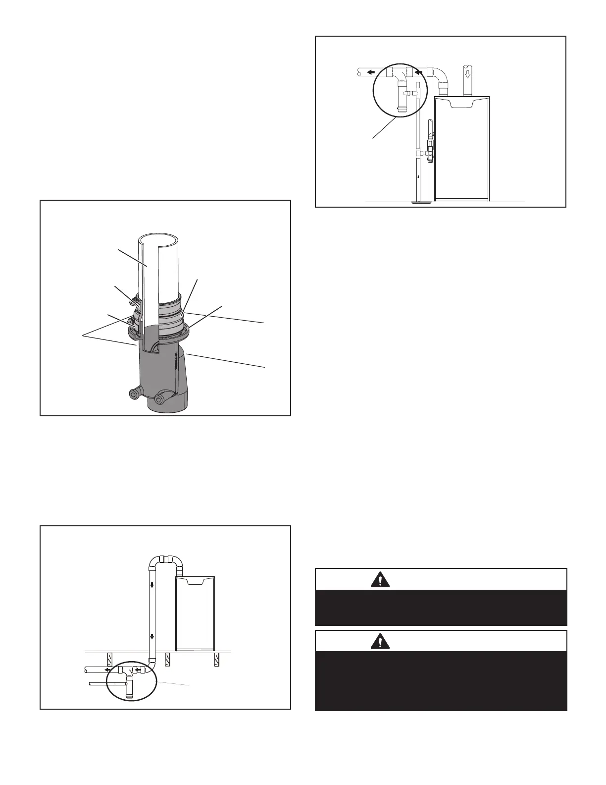
Crawl Space and Extended Horizontal Venting
Lennox provides kit 51W18(USA) and kit 15Z70 (Canada)
to install 2” or 3” PVC exhaust piping through the oor
joists and into the the crawl space. This kit can also be
used as a supplemental drain for installations with con-
densate run back in the vent pipe (ie. long horizontal runs,
unconditioned spaces, etc.). See FIGURE 27 and FIG-
URE 28
Venting In A Crawl Space
Basement Floor
KIT 51W18
(USA)
KIT 15Z70
(CANADA)
FIGURE 27
Long Horizontal Runs
KIT 51W18
(USA)
KIT 51Z70
(CANADA)
FIGURE 28
Guidelines for Vent Terminations
In Direct Vent applications, combustion air is taken from
outdoors and the ue gases are discharged to the out-
doors. The SLP99UHV is classied as a direct vent, Cate-
gory IV gas furnace.
In Direct Vent applications, the vent termination is limited
by local building codes. In the absence of local codes, re-
fer to the current National Fuel Gas Code ANSI Z223-1/
NFPA 54 in U.S.A., and current CSA-B149 Natural Gas
and Propane Installation Codes in Canada for details.
Position termination according to location given in gure
20. In addition, position termination so it is free from any
obstructions and 12” above the average snow accumula-
tion.
At vent termination, care must be taken to maintain protec-
tive coatings over building materials (prolonged exposure
to exhaust condensate can destroy protective coatings).
It is recommended that the exhaust outlet not be located
within 6 feet (1.8m) of an outdoor AC unit because the
condensate can damage the painted coating.
NOTE - See TABLE 9 for maximum allowed exhaust pipe
length without insulation in unconditioned space during-
winter design temperatures below 32°F (0°C). If required
exhaust pipe should be insulated with 1/2” (13mm) Ar-
maex or equivalent. In extreme cold climate areas, 3/4”
(19mm) Armaex or equivalent may be necessary. Insu-
lation must be protected from deterioration. Armaex with
UV protection is permissable. Basements or other en-
closed areas that are not exposed to the outdoor ambient
temperature and are above 32 degrees F (0°C) are to be
considered conditioned spaces.
IMPORTANT
Do not use screens or perforated metal in exhaust or
intake terminations. Doing so will cause freeze-ups and
may block the terminations.
IMPORTANT
For Canadian Installations Only:
In accordance to CSA International B149 installation
codes, the minimum allowed distance between the
combustion air intake inlet and the exhaust outlet of other
appliances shall not be less than 12 inches (305mm).
 Loading...


