Page 42
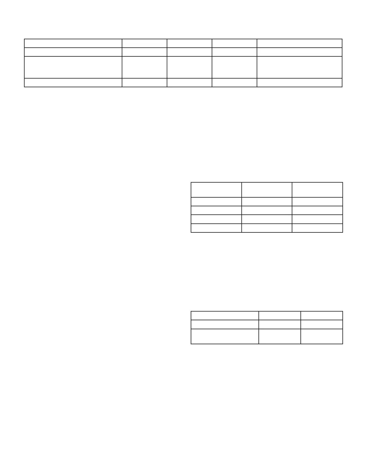
TABLE 16
Thermostat Selection Switch Settings
Operation Thermostat Switch 1 Switch 2 Switch 3
Variable Capacity Heat (35% to 100%) Two-Stage O On O
Three-Stage Heat
(35%, 70%, 100%)
Single-Stage On O
2nd stage delay OFF = 7 minutes
ON = 12 minutes 3rd stage delay
10 minutes xed
Two-Stage Heat (W1 70%, W2 100%) Two-Stage O O O
NOTE - When the SLP99UHV is used with a communicat-
ing thermostat, all indoor blower speed selections and DIP
switch settings are made by the thermostat.
SLP99UHV units are equipped with an integrated control.
This control manages ignition timing, combustion air induc-
er speed, heating mode fan o delays and indoor blower
speeds based on selections made using a communicating
thermostat or the control DIP switches and on-board links.
The control includes an internal Watchguard feature which
automatically resets the ignition control when it has been
locked out.
NOTE - All DIP switches are factory shipped in the
“OFF” position.
Heating Operation DIP Switch Settings -- FIGURE 55
Switch 1 -- Thermostat Selection -- This unit may be
used with either a single-stage or two-stage thermostat.
The thermostat selection is made using a DIP switch
which must be properly positioned for the particular appli-
cation. The DIP switch is factory-positioned for use with a
twostage thermostat. If a single-stage thermostat is to be
used, the DIP switch must be repositioned. See TABLE
16.
Switch 2 -- Operating Mode with Two-Stage Ther-
mostat -- If a two-stage thermostat is used, the furnace
can operate in either variable-capacity or conventional
twostage mode. When variable-capacity mode is select-
ed, the ring rate of the unit is varied to maximize comfort.
Conventional two-stage mode is the factory default set-
ting. See TABLE 16.
Switch 3 -- Second-Stage Heat On Delay -- If a single-
stage thermostat is used, the integrated control can be
used to energize second-stage heat after either 7 minutes
or 12 minutes of rst-stage heat operation. See TABLE 16.
Switches 4 and 5 -- Blower-O Delay -- The blower-on
delay of 30 seconds is not adjustable. The blower-o delay
(time that the blower operates after the heating demand
has been satised) can be adjusted by moving switches 4
and 5 on the integrated control. The unit is shipped from
the factory with a blower-o delay of 120 seconds. The
blower o delay aects comfort and is adjustable to sat-
isfy individual applications. Adjust the blower o delay to
achieve a supply air temperature between 90° and 110°F
at the exact moment that the blower is de-energized. Lon-
ger o delay settings provide lower supply air tempera-
tures; shorter settings provide higher supply air tempera-
tures. TABLE 17 provides the blower-o timings that will
result from dierent switch settings.
TABLE 17
Blower-O Delay Switch Settings
Blower-O Delay
(Seconds)
Switch 4
Switch 5
90 O On
120 (factory) O O
180 On O
210 On On
Indoor Blower Operation DIP Switch Settings
Switches 6 and 7 -- Continuous Indoor Fan Operation
Blower Speed -- The unit is shipped from the factory with
the DIP switches positioned for medium low (2) speed
during continuous indoor blower operation. The table be-
low provides the continuous blower speeds that will result
from dierent switch settings. Refer to tables beginning on
page 44 for corresponding cfm values.
TABLE 18
Continuous Indoor Blower Operation -- Blower Speeds
Speed Switch 6 Switch 7
1 - Low (28%)* O On
2 - Medium Low (38%)*
Factory
O O
* Percentage of high speed cooling
 Loading...


