Page 7
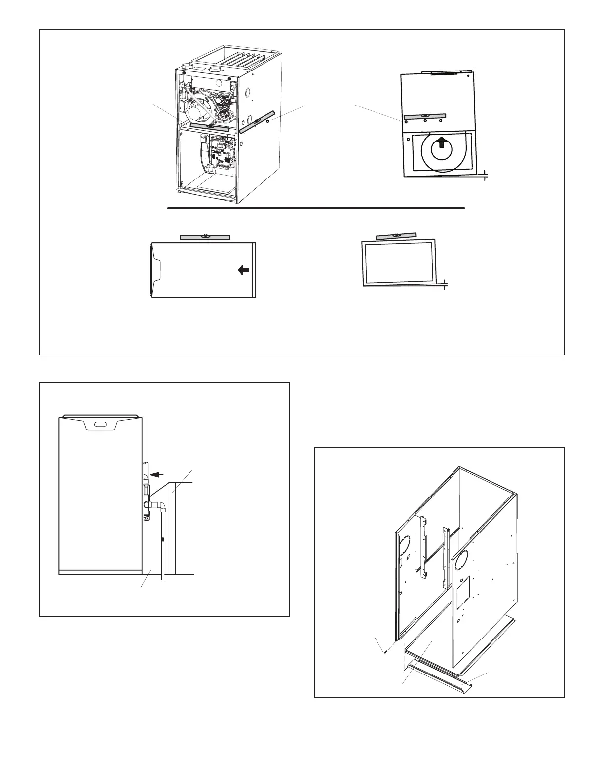
UPFLOW APPLICATION
HORIZONTAL APPLICAT ION
SIDE VIEW
FRONT VIEW
END VIEW
UNIT
FRONT
AIR FLOW
UNIT
FRONT
1/2”
max.
1/2”
max.
AIR FLOW
Unit must be level side-to-side. Unit may be positioned from level to 1/2” toward the front to aid in draining.
Place level on the front blower
deck to check side to side
Place level on blower
deck screws to check
forward tilt
FIGURE 5
(with transition and filter)
Return
Air
Plenum
Transition
20” X 25” X 1”
(508mmX635mmX
Air Filter
FIGURE 6
SLP99UHV applications which include side return air
and a condensate trap installed on the same side of
the cabinet (trap can be installed remotely within 5
feet) require either a return air base or eld-fabricated
transition to accommodate an optional IAQ accessory
taller than 14.5”. See FIGURE 6.
Removing the Bottom Panel
Remove the two screws that secure the bottom cap to the
furnace. Pivot the bottom cap down to release the bottom
panel. Once the bottom panel has been removed, reinstall
the bottom cap. See FIGURE 7.
Removing the Bottom Panel
Screw
Bottom Panel
Bottom Cap
FIGURE 7
 Loading...


