Page 38
B- Indoor Blower Motor
Power Choke
(4 and 5 Ton Only)
Blower Motor
(B3)
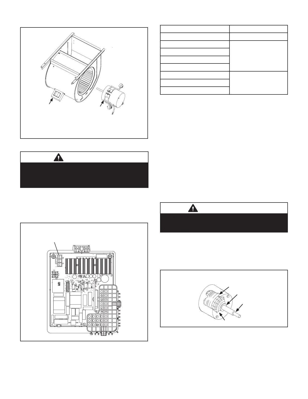
To Remove Blower From Unit: Remove access panels,
Control box, Bolts and Wiring Jackplugs.
Then Slide Out Front of Unit.
FIGURE 7
WARNING
During blower operation, the ECM motor emits
energy that may interfere with pacemaker operation.
Interference is reduced by both the sheet metal
cabinet and distance.
Blower Drive
Some units will be equipped with a blower drive shown in
FIGURE 8 with LED codes for operation in TABLE 12. The
blower drive is not repairable. If it fails replace the drive.
BLOWER DRIVE
Located in the control box
Three pin connector to
blower motor
FIGURE 8
TABLE 12
Led* Meaning
1 short blink Normal heartbeat
2 short blinks
Drive fault
replace drive
3 short blinks
4 short blinks
5 short blinks
1 long blink + 1short blink
Temporary fault
(see troubleshooting
page 52)
1 long blink + 2 short blinks
1 long blink + 3 short blinks
* Do not touch or remove drive for replacement until all
blinking lights are o. Blinking light(s) indicates drive still
has power.
The motor communicates with the integrated control via
a 2-way serial connection. The motor receives all neces-
sary functional parameters from the integrated control and
does not rely on a factory program like traditional variable
speed motors. Units use a three-phase, electronically
controlled D.C. brushless motor (controller converts single
phase a.c. to three phase D.C.), with a permanent-mag-
net-type rotor (FIGURE 9). Because this motor has a per-
manent magnet rotor it does not need brushes like con-
ventional D.C. motors.
The stator windings are split into three poles which are
electrically connected to the controller. This arrangement
allows motor windings to turn on and o in sequence by
the controller.
IMPORTANT
Earlier ECM motors used on other Lennox furnace
models are not interchangeable with motors used
on the SL280UHV furnace line.
A solid-state controller is permanently attached to the mo-
tor. The controller is primarily an A.C. to D.C. converter.
Converted D.C. power is used to drive the motor. The con-
troller contains a microprocessor which monitors varying
conditions inside the motor (such as motor workload).
STATOR
(WINDINGS)
OUTPUT
SHAFT
BEARING
FIGURE 9
The controller uses sensing devices to sense what posi-
tion the rotor is in at any given time. By sensing the posi-
tion of the rotor and then switching the motor windings on
and o in sequence, the rotor shaft turns the blower.

 Loading...


