Page 49
The gas valve is factory set and should not require adjust-
ment. All gas valves are factory regulated.
Manifold Adjustment Procedure:
1 - Connect test gauge to manifold pressure tap
(FIGURE 19 and FIGURE 20) on gas valve.
2 - Ignite unit on low re and let run for 5 minutes to
allow for steady state conditions.
3 - After allowing unit to stabilize for 5 minutes, record
manifold pressure and compare to value given in
TABLE 19.
4 - If necessary, make adjustments. FIGURE 19 and
FIGURE 20 show location of high re and low re
adjustment screw.
5 - Repeat steps 2, 3 and 4 on high re.
6 - Shut unit o and remove manometer as soon as an
accurate reading has been obtained. Take care to
replace pressure tap plug.
7 - Start unit and perform leak check. Seal leaks if
found.
F- Proper Gas Flow (Approximate)
Furnace should operate at least 5 minutes before check-
ing gas ow. Determine time in seconds for two revolu-
tions of gas through the meter. (Two revolutions assures
a more accurate time.) Divide by two and compare to time
in TABLE 17. If manifold pressure matches TABLE 19 and
rate is incorrect, check gas orices for proper size and
restriction.
NOTE- To obtain accurate reading, shut o all other gas
appliances connected to meter.
G- Proper Combustion
Furnace should operate minimum 15 minutes with correct
manifold pressure and gas ow rate before checking com-
bustion. See sections E- and F-. Take combustion sam-
ple beyond the ue outlet and compare to TABLE 18. The
maximum carbon monoxide reading should not exceed
100 ppm
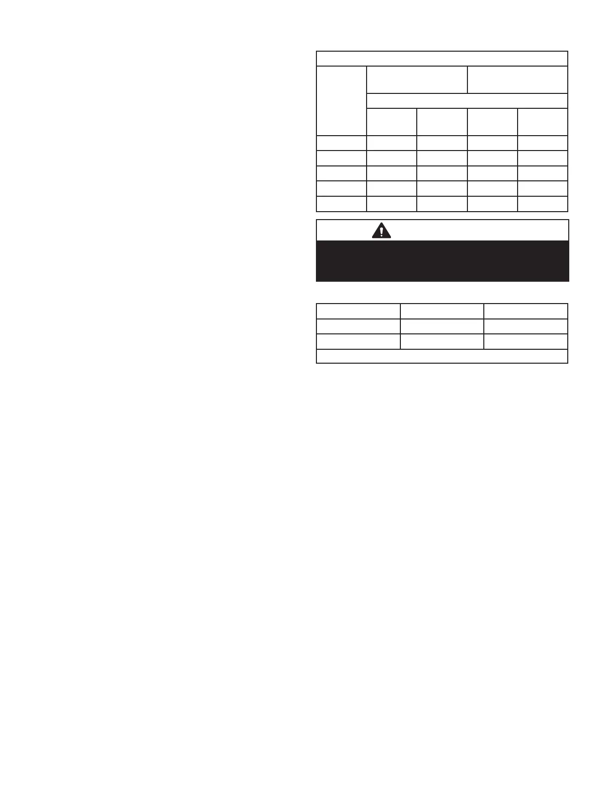
TABLE 17
GAS METERING CLOCKING CHART
SL280
Unit
Natural 1000 btu/
cu ft
LP 2500 btu cu/cu ft
Seconds For One Revolution
1 cu ft
dial
2 cu fr
dial
1 cu ft
Dial
2 cu ft
Dial
-045 80 160 200 400
-070 55 110 136 272
-090 41 82 102 204
-110 33 66 82 164
-135 27 54 68 136
IMPORTANT
For safety, shut unit o and remove manometer as
soon as an accurate reading has been obtained.
Take care to replace pressure tap plug.
TABLE 18
Firing Rate CO2% For Nat CO2% For L.P.
High Fire 6.8 - 7.4 7.5 - 9.0
Low Fire 4.2 - 5.7 5.0 - 6.0
The carbon monoxide reading should not exceed 100 ppm.
H- High Altitude
The manifold pressure, gas orice and pressure switch
may require adjustment or replacement to ensure proper
operation at higher altitudes. See TABLE 19 for manifold
pressures and TABLE 20, TABLE 21 and TABLE 22for
pressure switch and gas conversion kits.

 Loading...


