22
• The seal on the unit refrigerant piping connec-
tions should remain in place until the last pos-
sible moment. This will prevent dust or water
from getting into the refrigerant piping before it
is connected.
• Flow the pipework with dry (oxygen-free) nitro-
gen (2.9 psig or 3 CFH) during brazing to avoid
oxidation which may block the refrigerant piping.
• Do not use ux when brazing copper-to-copper
piping. Use phosphor copper brazing ller alloy
(BCuP) which does not require ux. Flux has a
harmful eect on refrigerant pipe.
• Use a wet cloth to insulate the shut o valve dur-
ing brazing.
• Use dedicated gauges and hoses with R-410A
equipment.
Pressure Test
• Follow the pressure test specications in Table 2
for proper pressure testing procedures.
• Ensure the unit service valves are fully closed
and haven’t become loose during transportation.
• Use oxygen-free nitrogen to pressure test to 650
psig and hold for 1 hour.
Evacuate System
• Follow the Lennox pressure test specications
in table 1 and the triple evacuation process de-
scribed on this page to pressure test and evacu-
ate the system.
• Use a vacuum pump capable of evacuating to
lower than 500 Microns (0.5 Torr).
• Do not open any of the outdoor unit shut-o
valves (possible max 5 valves). The outdoor unit
does not need to be evacuated.
• Evacuate the system to 500 Microns (0.5 Torr), or
below, for 4 hours.
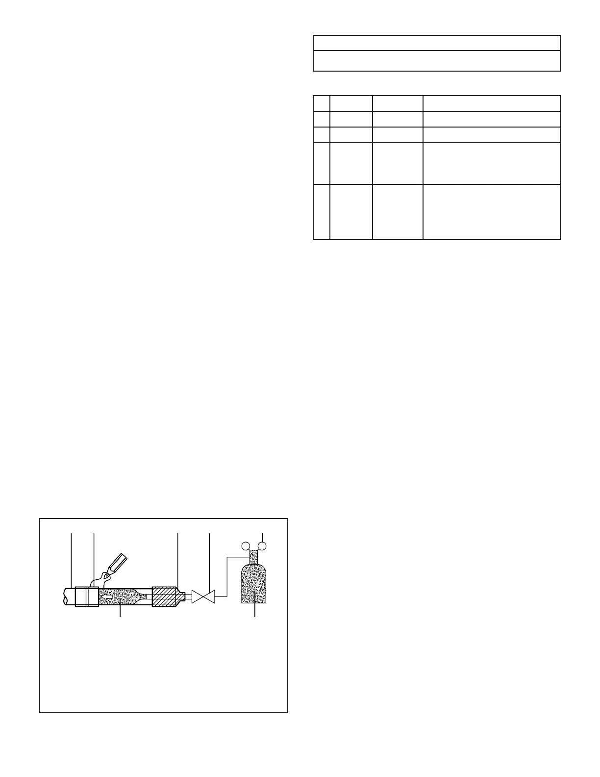
1 - Refrigerant pipe
2 - Part to be brazed
3 - Reducer
4 - Isolation valve
5 - Pressure-regulating valve
6 - Oxygen-free nitrogen
Figure 21. Brazing Best Practices
Table 2. Pressure Test Specications
1 3 bar 44 psig minimum of 10 minutes
2 15 bar 220 psig minimum of 10 minutes
3 32 bar 470 psig minimum of 10 minutes
4 45 bar 500 psig 1 hour. Stress test to
prove the integrity of the
complete installation.
5 32 bar 470 psig 24 hours. Lower system
pressure test, after
conrmation No. 4 was
successfully completed.
Triple Evacuation Procedure
A Micron or Torr gauge must be used for this
procedure.
1. Discharge the oxygen-free nitrogen and evacuate
the system to a reading of 8000 Microns (8 Torr)
using all service valves.
2. Break the vacuum by allowing nitrogen into the
three inter-connecting pipework port connections
(low pressure gas pipe, high pressure gas pipe
and liquid line pipe) until a positive pressure is
achieved.
3. Evacuate the system to a reading of 5000
Microns (5 Torr).
4. Break the vacuum by allowing nitrogen into the
three inter-connecting pipework port connections
(low pressure gas pipe, high pressure gas pipe
and liquid line pipe) until a positive pressure is
achieved
5. Evacuate the system to a minimum reading of
500 Microns (0.5 Torr).
6. For a moisture free system, ensure the vacuum
is held without movement for a minimum of 4
hours.
7. If pressure loss is detected, carry out steps 2
through 6 until no pressure loss is observed.
IMPORTANT!
Use only oxygen-free nitrogen (OFN).
 Loading...