13
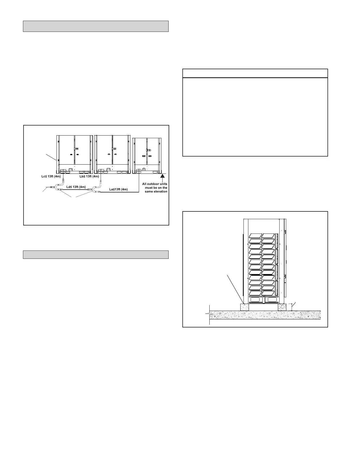
• A VRF system consisting of more than two
outdoor units must be placed in order from the
largest to the smallest capacity. See gure 8.
• The largest capacity outdoor unit must be
installed closest to the main pipe leading into the
building. See Figure 11.
• The largest capacity outdoor unit address is the
main unit, while the others are the sub units. See
Figure 11.
• All of the outdoor units manifolded together
should be installed at the same elevation.
Figure 11. Main/Sub Unit Placement
(40-Ton System Example)
Installation
Slab or Roof Mounting
Install the unit a minimum of 8 inches (203 mm)
above the roof or ground surface to avoid ice build-
up around the unit. Locate the unit above a load-
bearing area of the roof that can adequately support
the unit. Consult local codes for rooftop applications.
• Use a eld supplied slab or suitably sized
steelwork to construct a base for locating
the condensing unit. All supporting work
should be veried by a qualied engineer.
NOTE - Prefabricated light duty equipment pads
are NOT suitable for use.
• Support the unit across the front and back of the
unit.
IMPORTANT!
Roof Damage!
This system contains both refrigerant and
oil. Some rubber roong material may absorb
oil. This will cause the rubber to swell when
it comes into contact with oil. The rubber will
then bubble and could cause leaks. Protect the
roof surface to avoid expo sure to refrigerant
and oil during service and instal lation. Failure
to follow this notice could result in damage to
roof surface.
• If the unit coil cannot be installed away from
prevailing winter winds, a wind barrier should
be constructed. Size barrier at least the same
height and width as outdoor unit. Install barrier
12 inches (305 mm) minimum from the sides of
the unit in the direction of prevailing winds.
Figure 12. Secure Outdoor Unit
to Approved Structure
Main/Sub Outdoor Unit Placement
NOTE - All of the outdoor units manifolded
together should be installed at the same elevation.
Main piping
to building
Outdoor Unit
Branch Pipe Kits
16-ton
Main unit
placed
closest to
main pipe
leading into
building
14-ton 10-ton
Use lag
bolts (4) to
secure unit
to slab or
approved frame
at each corner
8 in.
(203 mm)
Securing Outdoor Unit to Slab or Frame
Use lag bolts (min. 3/8 in.) at all four corners to
secure the unit to the eld-provided slab or frame.
Isolation material can be used to control vibration or
sound transmission. Lag bolts must extend through
material to the slab or frame. See Figure 12.
 Loading...