EasyManua.ls Logo

Lennox VRB Series

Lennox VRB Series
48 pages
To Next Page IconTo Next Page
Loading...
1
INSTALLATION/OPERATION
INSTRUCTIONS
VRB Heat Recovery
VRF SYSTEMS
OUTDOOR UNITS
507885-03
05/2019
THIS MANUAL MUST BE LEFT WITH THE
OWNER FOR FUTURE REFERENCE
These instructions are intended as a general guide and do
not supersede local codes in any way. Consult authorities
having jurisdiction before installation.
Shipping and Packing List
General
Check the components for shipping damage. If you
nd any damage, immediately contact the last car-
rier. Package 1 of 1 contains the following:
1 - Assembled VRB heat recovery outdoor unit
1 - Outdoor unit installation instruction
1 - Piping accessory package
The VRB heat recovery outdoor units are matched
with up to 64 indoor units per system to create a VRF
(variable refrigerant ow) system that uses HFC-
410A refrigerant.
Refer to the Product Specication bulletin (EHB)
for the proper use of these heat recovery units with
matching indoor units, mode selection boxes, branch
pipes, line sets and controls.
WARNING
!
Improper installation, adjustment, alteration,
service or maintenance can cause property
damage, personal injury or loss of life.
Installation and service must be performed
by a licensed professional HVAC installer (or
equivalent) or service agency.
Failure to follow safety warnings and these
instruc tions exactly could result in property
damage, dan gerous operation, serious injury,
or death.
Any additions, changes, or conversions
required in order for the appliance to
satisfactorily meet the ap plication needs must
be made by a licensed profes sional HVAC
installer (or equivalent) using factory-specied
parts.
Do not use this system if any part has been
under water. A ood-damaged appliance is
extremely dan gerous. Immediately call a
licensed professional HVAC service technician
(or equivalent) to inspect the system and to
replace all controls and electrical parts that
have been wet, or to replace the system, if
deemed necessary.
Do not change the settings of any protection
devices installed in the outdoor unit. If the
pressure switch, thermal switch, or other
protection device is shorted or forcibly
operated, re or explosion may occur.
Do not use parts other than those specied by
Lennox or re and/or explosion may occur.
WARNING
!
IMPORTANT
The Clean Air Act of 1990 bans the intentional
venting of refrigerant (CFC’s and HCFC’s) as of
July 1, 1992. Approved methods of recovery,
recycling or reclaiming must be followed. Fines
and/or incarceration may be levied for non-
compliance.
These units must be installed as part of a
matched system as specied in the Product
Specications (EHB) bulletin.
CAUTION
As with any mechanical equipment, contact
with sharp sheet metal edges can result in
personal injury. Take care while handling this
equipment and wear gloves and protective
clothing.
©2018 Lennox Industries Inc. Dallas, Texas, USA
VRF

Table of Contents

Question and Answer IconNeed help?

Do you have a question about the Lennox VRB Series and is the answer not in the manual?

Lennox VRB Series Specifications

General IconGeneral
BrandLennox
ModelVRB Series
CategoryHeating System
LanguageEnglish

Summary

VRB Heat Recovery Installation

Critical Safety and Handling Instructions

Covers critical safety notices regarding operation, handling, and warnings.

Unit Overview and Packing Details

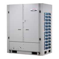
Describes the VRB heat recovery outdoor units and lists components in the shipping package.

Safety Requirements and Model Identification

Electrical Safety and Fire Hazards

Warns against electrical shock, fire, or explosion hazards during unit operation.

Model Number Decoding

Explains the coding system used for identifying VRF outdoor unit model numbers.

System Piping Design Caution

Emphasizes following engineered piping designs and reporting any changes.

Outdoor Unit Dimensions and Weights

Outdoor Unit Dimensions (Continued)

Piping Details and Valve Layouts

Outdoor Unit Placement Guidelines

Clearance and Interference Considerations

Details essential considerations for outdoor unit placement, including clearances and interference.

Environmental Installation Factors

Specifies distances from exhaust vents and recommendations for coastal installations.

Unit Lifting and Handling

Obstruction Clearances for Airflow

Front Service Access Clearance

Defines required clearance in front of the unit for access to service doors.

Perimeter Airflow Obstruction Clearance

Specifies clearance requirements around the unit to avoid air recirculation.

Overhead Airflow Obstruction Clearance

Details clearance needed above the unit to ensure proper discharge airflow.

Cold Climate Installation Considerations

Snow, Ice, and Drifting Protection

Advises on locating units away from snow/ice hazards and installing protective measures.

Unit Support and Weather Resistance

Illustrates securing units to weather-resistant supports and managing defrost water.

Wind Protection and Air Discharge Ducting

Prevailing Wind Protection Strategy

Guides on unit placement to avoid direct exposure to winter prevailing winds.

Air Discharge Duct Installation Rules

Details requirements for installing air discharge ducts, including design and louvers.

Static Pressure Configuration Options

Table showing static pressure settings and corresponding descriptions for unit configuration.

Air Discharge Duct Design Specifications

Discharge Duct Airflow Performance Curves

Multi-Unit System Configuration

Outdoor Unit Arrangement and Elevation

Details rules for arranging multiple outdoor units based on capacity and elevation.

Mounting and Securing the Outdoor Unit

Provides guidelines for mounting units on slabs or roofs, emphasizing structural support.

Refrigerant Piping Procedures and Safety

Handling Refrigerant Leaks Safely

Warns about refrigerant leaks and provides safety procedures for handling them.

General Refrigerant Piping Best Practices

Outlines essential practices for refrigerant piping, including insulation and connection methods.

Piping Length Limits and Support Contact

Lists system piping length limits and advises contacting support for assistance.

Maximum Refrigerant Piping Limits

Refrigerant Piping Diagrams and Selection

Pipe Size Selection Guides

Outdoor Unit Main Pipe Sizing

Offers tables for selecting main pipe diameters for outdoor units based on capacity.

Indoor Unit Main Pipe Sizing

Provides tables for selecting indoor unit main pipe diameters based on capacity.

Outdoor Unit Connection Pipe Sizing

Details pipe selection for outdoor unit connection pipes.

Outdoor Unit Branch Pipe Assembly Selection

Specifies selection criteria for outdoor unit branch pipe assemblies.

Indoor Unit Auxiliary Pipe Sizing

Guides selection of indoor unit auxiliary pipes based on capacity.

Indoor Unit Branch Pipe Kit Details

Mode Selection Box Piping Kit Diagrams

Branch Pipe Kit Installation Orientation

Branch Pipe Kit Cutting Procedure

Branch Pipe Kit Placement Guidelines

Refrigerant System Testing and Evacuation

Proper Brazing Techniques

Details best practices for brazing refrigerant piping, including nitrogen flow and flux usage.

Refrigerant System Pressure Testing

Outlines the specifications for performing pressure tests on the refrigerant system.

Triple Evacuation Method

Describes the step-by-step procedure for triple evacuation of the refrigerant system.

Calculating Additional Refrigerant Charge

Additional Refrigerant Charge Data Tables

Refrigerant Charge Calculation Example

Refrigerant Discharge Safety Standards

Manifolded Outdoor Unit Connection

Piping and Installation for Multiple Units

Details how to connect and install multiple outdoor units together, ensuring proper piping.

Parallel Piping Connections

Manifolded Unit Piping Size Specifications

Triple-Module Outdoor Unit Branch Pipe Kits

Mode Selection Box Installation and Connectivity

Mode Selection Box Mounting and Piping Rules

Outlines installation rules, piping connections, and operational modes for mode selection boxes.

Mode Selection Box Wiring Diagrams

Electrical Wiring Safety and Practices

Power Supply and Circuit Protection Warnings

Provides critical safety warnings regarding power supply, wiring, and circuit protection.

Unit Grounding and Wiring Installation

Details proper grounding, wiring installation, and avoiding interference for the unit.

Terminal Block Identification

Identifies power and communication terminal strips and their connection points.

VRB Wiring Diagrams (230 V Models)

VRB Wiring Diagrams (460 V Models)

VRB Wiring Diagrams (230 V Specific Models)

VRB Wiring Diagrams (460 V Specific Models)

Outdoor Unit Main Board Components

Digital Display Functionality

Explains the functions of the digital display for normal and operating modes.

Main Board Port and Component Mapping

Identifies and describes the various ports and components on the main board.

LCD Display Operation and Navigation

User Interface and Menu Access

Guides on navigating the LCD display, using buttons, and entering the service tool.

Home Screen Information Display

Details the information displayed on the main screen, including voltage, mode, and status.

System Menu Structure Overview

System Settings and Configuration Parameters

Installation and DIP Switch Configuration

Covers parameters for installation info, commission date, and DIP switch settings.

Operational Function Settings

Details settings for indoor temperature units, priority, lockout, target temperatures, and demand control.

Service Mode Operations and Procedures

Explains how to perform operations like test runs, defrost, and refrigerant recycling.

VRB Electrical Data Specifications

Dip Switch and Dial Configuration Settings

Outdoor Unit DIP Switch Settings

Details DIP switch settings for configuring the outdoor unit type and temperature sensor.

Indoor Unit Quantity and Network Address Settings

Explains DIP switch settings for indoor unit quantity and network address assignment.

Silent Mode Configuration Options

Outlines the various silence mode settings available for the outdoor unit.

Settings and Functions Reference

Service Mode Functions List

Lists functions available within the Service Mode, such as testing and defrost.

Operational Settings and Mode Management

Describes settings for snow blowing mode, temperature units, and energy saving.

System Parameter Query Instructions

Navigating and Querying System Data

Explains how to navigate and query system parameters using SW3 and SW4 buttons.

System Parameter Definitions

Lists various system parameters, their descriptions, and value units for monitoring.

System Parameter Query Continuation

Reserved Parameters and Software Version

Details reserved parameters, software version, and notes on display functionality.

Electrical Installation Power Wiring

Typical Power Wiring Diagram

Illustrates the typical power wiring connections for indoor and outdoor units.

VRB Communication Wiring Diagram

Typical Communication Wiring Connections

Shows the typical communication wiring diagram between units and boxes.

Troubleshooting Error Codes

Digital Display Error Code Definitions

Lists error codes displayed on the digital display and their corresponding definitions.

Technical Support Resources

Related product manuals