11
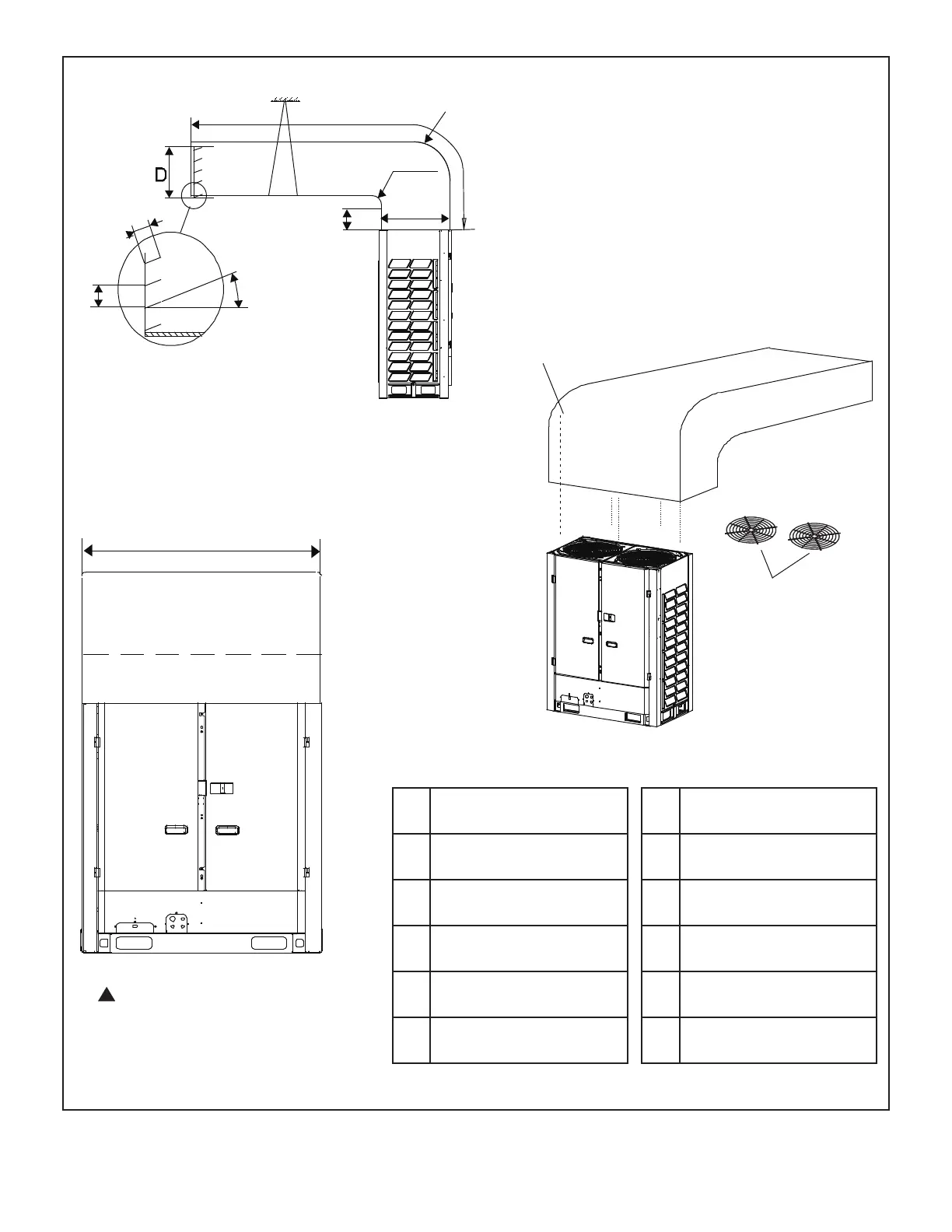
Figure 10. Air Discharge Duct
(Front or Rear Connection)
072, 096, 120 -- 50-3/4 in. (1289 mm)
144, 168, 192 -- 65 in. (1651 mm)
Air Outlet Louver
F
A
C
B
4 in. (102 mm)
E
Radius
Radius
Support
≤ 15°
3-1/2 in.
(89 mm)
Fan guards
(remove
first)
8 × ST3.9
self-threading screws
A A ≥ 12 in.(305 mm)
B B ≥ 10 in. (254 mm)
C C ≤ 118-1/8 in. (3000 mm)
D D ≥ 24 in. (610 mm)
E E = A + 24 in. (610 mm)
F 24 in. (610 mm)
072, 096, 120
A A ≥ 12 in.(305 mm)
B B ≥ 10 in. (254 mm)
C C ≤ 118-1/8 in. (3000 mm)
D D ≥ 28-3/8 in. (721 mm)
E E = A + 24 in. (610 mm)
F 28-3/8 in. (721 mm)
144, 168, 192
!
Contact the Lennox VRF
applications department for
assistance with ducting applications
that dier from these images.
 Loading...