45
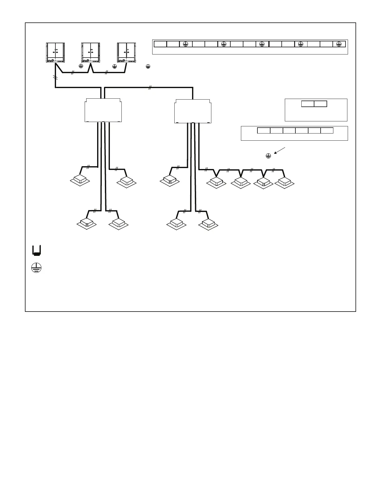
Figure 35. VRB Heat Recovery Typical Communication Wiring
NOTE - Each communication wire from the MS box should follow the refrigerant piping for that port.
P Q
All Drain Wires will connect from outdoor unit chassis to mode selection box chassis at the end of
the signal run.
18 GA., stranded, 2-conductor, shielded control wire (polarity sensitive).
Typical Wiring Diagram, NEC/CEC and Local Codes apply.
Outdoor unit Outdoor unit
(sub1 unit)
Outdoor unit
(sub2 unit)
(PQ)
(main unit)
(PQ)
MS
Box
(PQ)
(PQ)
MS
Box
(PQ)
(PQ)
(H1 H2 )
(H1 H2 ) (H1 H2 )
Outdoor Unit Communication Terminal Block
P Q H1 H2X YO AK1 K2
MS Box Communication
Terminal Block
P Q
Indoor Unit Communication Terminal Block
HA HB 12V COM P Q
Ground drain wire or
cable shield
to MS Box
and Outdoor Unit chassis
Install a terminating resistor (Ω120) on terminals P&Q on the indoor unit
which is furthest from the outdoor unit.
 Loading...