1
©2017 Lennox Industries Inc. Dallas, Texas, USA
INSTALLATION
INSTRUCTIONS
THIS MANUAL MUST BE LEFT WITH THE OWNER
FOR FUTURE REFERENCE
Shipping and Packing List
General
Check the components for shipping damage. If you
nd any damage, immediately contact the last carrier.
Package 1 of 1 contains the following:
1 - Assembled indoor unit
2 - Condensate plugs
2 - Rubber grommets
1 - Water level switch cable
1 - 5/8 to 1/2 adapter (VVCA018)
1 - 3/8 to 1/4 adapter (VVCA018)
1 - Water level switch cable
1 - Installation manual
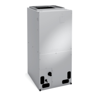
VVCA Vertical Air Handler
The VVCA air handler is designed for indoor installation
only. As shipped, the unit is ready for installation in upow
and horizontal-right air discharge applications. Field-
congurable for horizontal left-air discharge.
The unit has accessible electrical controls, refrigerant
piping connections and an internally mounted expansion
valve kit. This unit is also equipped with variable speed
blower motor.
Refer to the Product Specication bulletin (EHB) for the
proper use of these indoor units with specic heat pumps,
heat recovery units, mode switching devices, branch
pipes, line sets and controls.
These instructions are intended as a general guide and do
not supersede local codes in any way. Consult authorities
having jurisdiction before installation.
The air handler is shipped from the factory completely
assembled. This unit is provided with anges for
connecting the supply plenum.
VRF
VRF SYSTEMS -- Air Handler
507539-05
11/2018
WARNING
Improper installation, adjustment, alteration, ser vice or
maintenance can cause property damage, personal
injury or loss of life.
Installation and service must be performed by a li censed
professional HVAC installer, service agency or the gas
supplier.
Failure to follow safety warnings and these instruc tions
exactly could result in property damage, dan gerous
operation, serious injury, or death.
Any additions, changes, or conversions required in order
for the appliance to satisfactorily meet the ap plication
needs must be made by a licensed profes sional HVAC
installer (or equivalent) using factory-specied parts.
Do not use this system if any part has been under water.
A ood-damaged appliance is extremely dan gerous.
Immediately call a licensed professional HVAC service
technician (or equivalent) to inspect the system and to
replace all controls and electrical parts that have been
wet, or to replace the system, if deemed necessary.
IMPORTANT
The Clean Air Act of 1990 bans the intentional venting
of refrigerant (CFCs, HCFCs and HFCs) as of July 1,
1992. Approved methods of recovery, recycling or
reclaiming must be followed. Fines and/or incarceration
may be levied for noncompliance. These units must be
installed as a part of a matched system as specied in
the Product Specications (EHB) bulletin.
CAUTION
As with any mechanical equipment, contact with sharp
sheet metal edges can result in personal injury. Take
care while handling this equipment and wear gloves and
protective clothing.