11
Condensate Piping Connections
The air handler is provided with ¾” NPT condensate
drain connections.
Do not overtighten drain fitting.
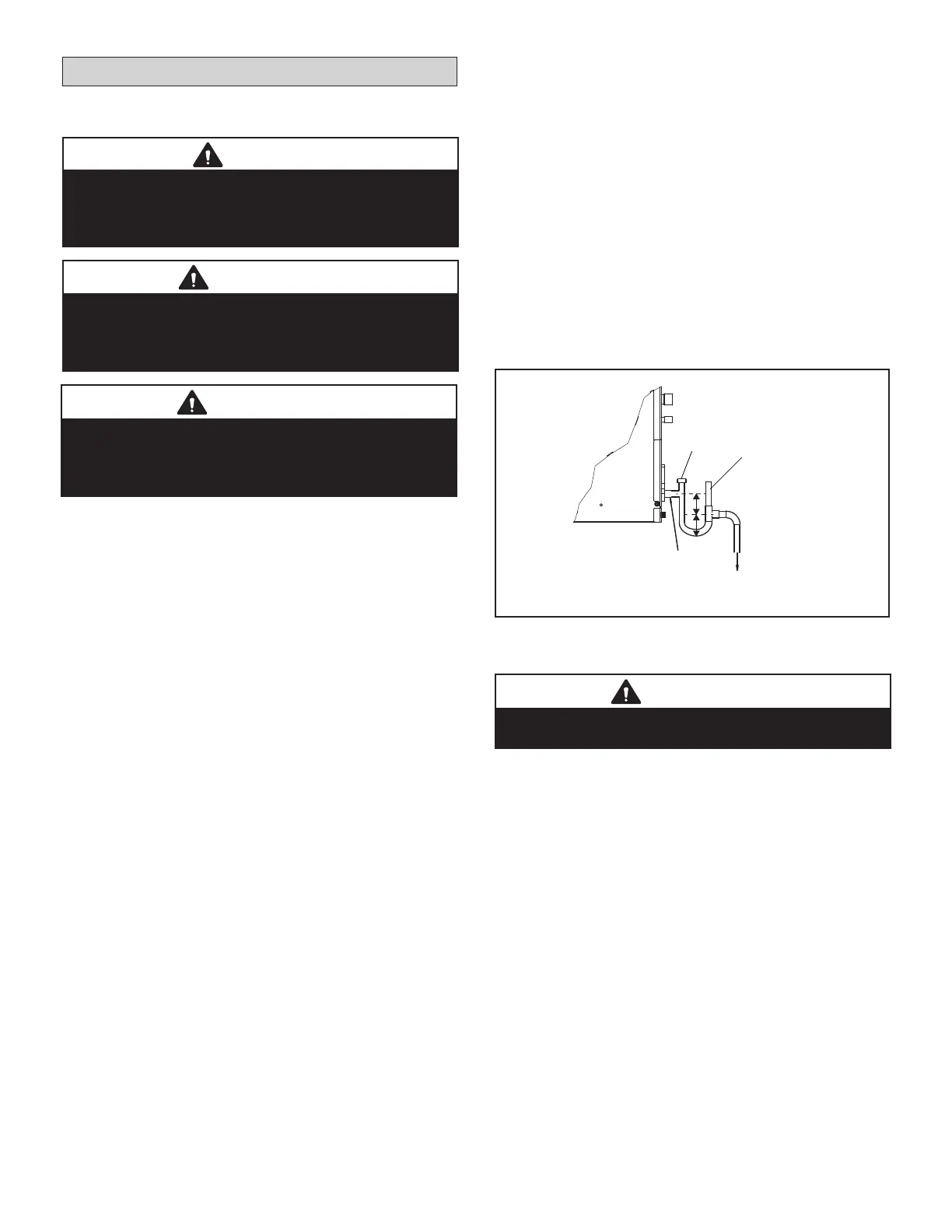
Unit must be slightly inclined toward drain connection.
Unit
To approved drain
Do not operate unit without condensate drain trap.
3”
3”
Clean Out
Do not glue
Anti-siphon vent must
extend above the height
of the coil drain pan by
2” (51 mm).
Figure 11. Condensate Drain Trap
1. Install properly sized, eld-provided connection
ttings and connect primary drain line to
the main drain pan connection (3/4” I.D.).
NOTE - When installing drain line connection ttings to the
drain pan, hand tighten the tting and use a thread sealant.
Over-tightening the ttings can split connections on the drain
pan.
2. If the secondary drain line is to be used, remove
the plug or the knockout and route the drain line
so that water draining from the outlet will be easily
noticed by the user. Refer to local codes for drain
trap requirements on the secondary drain line.
3. Check again to ensure drain ports and drain pan are
free of all debris.
4. Plug and check any unused drain pan openings for
tightness to prevent water leaks or seepage from the
drain pan.
5. Install a 3” trap in the main (primary) drain lines as
close to the unit as practical (see gure 11). Make
sure the top of the trap is below the connection to
the drain pan to allow complete drainage of the pan.
NOTE - Horizontal runs must have an anti-siphon air
vent (standpipe) installed ahead of the horizontal run.
See gure 11. An extremely long horizontal run may
require an oversized drain line to eliminate air traps.
NOTE - Do not operate air handler without a trap in
the main (primary) drain. The condensate drain is on
the negative pressure side of the blower; therefore,
air being pulled through the condensate line will not
allow positive drainage without a proper trap.
6. Route the drain line to the outside or to an
appropriate drain. Drain lines must be installed
so they do not block service access to the front
of the air handler. A 24” clearance is required for
lter, coil, or blower removal and service access.
NOTE - Check local codes before connecting the
drain line to an existing drainage system. Insulate
the drain lines where sweating could cause water
damage.
7. After the system installation is complete, the
condensate drain line must be checked for leaks
and proper drainage. If a eld-provided condensate
pump has been installed, it must be checked to
ensure proper operation. This check is part of the
commissioning sequence.
Using an External Water Level Switch
Disconnect the closed circuit loop, CN 5. Connect the
water level switch cable accessory to CN 5. See unit
wiring diagrams for location of CN 5.
The connection has 5 VDC current, do not supply eld
voltage.
IMPORTANT
Drain should have a slope of at least 1/4 inch per foot
and should be approved corrosion-resistant pipe. You
must conrm operation of every drain and pump in the
system as part of the commissioning procedure.
IMPORTANT
A eld-fabricated secondary drain pan, with a drain pipe
to the outside of the building, is required in all installa-
tions over a nished living space or any area that may
be damaged by overow from the main drain pan.
CAUTION
Make sure that drain piping is properly routed and
insulated in order to prevent both leaks and condensation.
Follow these instructions exactly to ensure proper
drainage and unit operation.
IMPORTANT
You must conrm operation of every drain and pump in
the system as part of the commissioning procedure.
 Loading...